When first looking at the blueprint for the CCNA/CCNP/CCIE Data Center track, one of my biggest fears was storage. My entire career thus far has been based on traditional IP data networks, not storage networks. I’m used to things like MAC addresses and IP addresses, not WWPNs and FCIDs. This is a completely foreign technology to most Network Engineers. You have to think back, at some point we were young and hopeful CCNAs-to-be, we knew nothing, but that didn’t stop us! Intimidation is over-rated, so throw fear aside and know that persistence always wins.
So you’ve read all about FC, and now you want to see how to configure it. In this blog post I’ll be going through a basic FC configuration, covering some fundamental Fibre Channel topics along the way, such as:
VSANs
FLOGI
FCNS
Trunking
Zoning (Basic and Enhanced)
FC Aliases
Device Aliases
Domain ID Modification
FSPF (with traffic engineering)
SAN Port-channels
As always, I highly recommend reading through the entire Cisco.com config guides, utilize your free account on CiscoLive365, and if you can afford it, get yourself an account with a trusted training provider like INE or IPexpert.
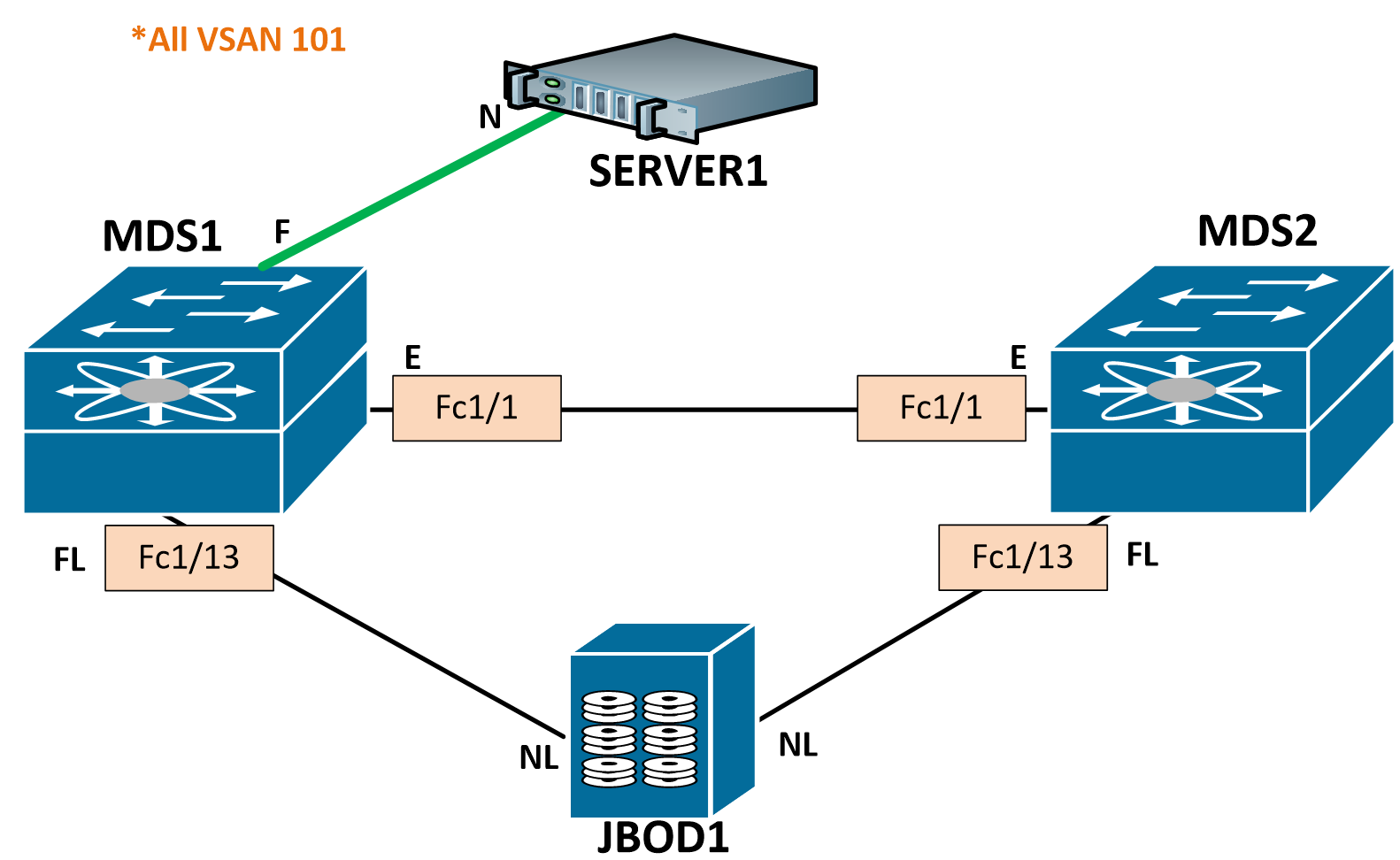
The topology we’ll be following is detailed below. I’m going to walk through with just a single VSAN, but you very well could run multiple. I’ll be doing future posts running two VSANs, its just less redundant configuration to worry about when learning fundamental FC topics. All links will be shutdown and we’ll start with a default configuration.

Let’s hop into MDS1. Notice our FLOGI and FCNS databases are empty (more on this in a minute):
MDS1# show flogi data
No flogi sessions found.
MDS1# show fcns data
There are no entries in the database
A quick recap for you on some FC basics:
Fibre Channel switches have Domain IDs that are used to identify them in the fabric. They are automatically assigned by the principal switch, which is automatically elected (no configuration necessary). You can statically assign Domain IDs if desired.
When a device connects to the fabric switch, it will perform a fabric login (FLOGI). This tells the fabric about your World Wide Node Name (WWNN) and World Wide Port Names (WWPN). Think of WWNs like MAC addresses in the ethernet world. They are burned-in physical addresses. WWPNs are used in zoning.
The fabric will then assign a logical Fibre Channel ID (FCID) to each WWPN, which will be used for switching in the data plane. Think of these like IP addresses.
Fibre Channel Name Server (FCNS) is used to create the WWPN-to-FCID table. Think of this like the ARP cache or DNS.
As you can see, I only have one VSAN configured right now, and have an automatically assigned Domain ID of 125:
MDS1# show fcdomain domain-list

VSAN 1
Number of domains: 1
Domain ID              WWN
---------    -----------------------
0x7d(125)    20:01:00:0d:ec:54:63:81 [Local] [Principal]
Configure a VSAN
VSANs are virtual SANs, almost like VLANs in how they separate domains. Each VSAN will have its own FLOGI, FCNS, principal switch, zoning, aliases, etc. We will first want to create our desired VSAN, then add our desired interfaces to that VSAN.

MDS1# conf t
Enter configuration commands, one per line.  End with CNTL/Z.
MDS1(config)# vsan database
MDS1(config-vsan-db)# vsan 101
MDS1(config-vsan-db)# vsan 101 name VSAN101
MDS1(config-vsan-db)# vsan 101 interface fc1/13

MDS1(config)# interface fc1/13
MDS1(config-if)# no shut
MDS1(config-if)# 2014 Aug 15 22:22:11 MDS1 %PORT-5-IF_UP: %$VSAN 101%$ Interface fc1/13 is up in mode FL

MDS1# show interface fc1/13 brief

-------------------------------------------------------------------------------
Interface  Vsan   Admin  Admin   Status          SFP    Oper  Oper   Port
                  Mode   Trunk                          Mode  Speed  Channel
                         Mode                                 (Gbps)
-------------------------------------------------------------------------------
fc1/13     101    auto   on      up               swl    FL      2    —
Often times MDS ports will auto-negotiate their Port types (F, FL, etc). In this case, we can see the operational mode was negotiated to FL. This is a Fabric Loop port since we are connecting to a JBOD.
FLOGI
Upon enabling these interfaces, the JBOD’s 8 disks sent a Fabric Login (FLOGI) to the switch. The FLOGI database is local to the switch. Each disk will have 1 WWNN and 2 WWPNs (1 for each port). Since we only have one port up right now, we will only see one WWPN for each disk.
MDS1# show flogi database
--------------------------------------------------------------------------------
INTERFACE        VSAN    FCID           PORT NAME               NODE NAME
--------------------------------------------------------------------------------
fc1/13           101   0x0100da  21:00:00:1d:38:1c:79:0a 20:00:00:1d:38:1c:79:0a
fc1/13           101   0x0100dc  21:00:00:1d:38:1c:6f:24 20:00:00:1d:38:1c:6f:24
fc1/13           101   0x0100e0  21:00:00:1d:38:1c:78:fa 20:00:00:1d:38:1c:78:fa
fc1/13           101   0x0100e1  21:00:00:1d:38:1c:78:d9 20:00:00:1d:38:1c:78:d9
fc1/13           101   0x0100e2  21:00:00:1d:38:0e:d9:5e 20:00:00:1d:38:0e:d9:5e
fc1/13           101   0x0100e4  21:00:00:1d:38:1c:76:af 20:00:00:1d:38:1c:76:af
fc1/13           101   0x0100e8  21:00:00:1d:38:1c:77:04 20:00:00:1d:38:1c:77:04
fc1/13           101   0x0100ef  21:00:00:1d:38:1c:76:db 20:00:00:1d:38:1c:76:db

Total number of flogi = 8.
Notice FCIDs were already assigned. The FCID is comprised of the switch’s Domain ID, Area ID and Port ID.
0x0100da
01 = Domain ID
00 = Area ID
da = Port ID
You can see the Domain ID now assigned to VSAN 101:
MDS1(config)# sh fcdomain domain-list

VSAN 1
Number of domains: 1
Domain ID              WWN
---------    -----------------------
0x7d(125)    20:01:00:0d:ec:54:63:81 [Local] [Principal]

VSAN 101
Number of domains: 1
Domain ID              WWN
---------    -----------------------
  0x01(1)    20:65:00:0d:ec:54:63:81 [Local] [Principal]
FCNS
We can also check out the FCNS database. The FCNS database is global to the fabric. Since there are no other switches in the fabric yet, we see the same output as the FLOGI database. Cool thing is you can see the port types, notice the NL (Node Loop).
MDS1# show fcns database

VSAN 101:
--------------------------------------------------------------------------
FCID        TYPE  PWWN                    (VENDOR)        FC4-TYPE:FEATURE
--------------------------------------------------------------------------
0x0100da    NL    21:00:00:1d:38:1c:79:0a                 scsi-fcp:target
0x0100dc    NL    21:00:00:1d:38:1c:6f:24                 scsi-fcp:target
0x0100e0    NL    21:00:00:1d:38:1c:78:fa                 scsi-fcp:target
0x0100e1    NL    21:00:00:1d:38:1c:78:d9                 scsi-fcp:target
0x0100e2    NL    21:00:00:1d:38:0e:d9:5e                 scsi-fcp:target
0x0100e4    NL    21:00:00:1d:38:1c:76:af                 scsi-fcp:target
0x0100e8    NL    21:00:00:1d:38:1c:77:04                 scsi-fcp:target
0x0100ef    NL    21:00:00:1d:38:1c:76:db                 scsi-fcp:target

Total number of entries = 8
Let’s go ahead and bring MDS2 up to speed:
MDS2# show flogi data
No flogi sessions found.
MDS2# show fcns data
There are no entries in the database
MDS2# sh int fc1/13 brief

-------------------------------------------------------------------------------
Interface  Vsan   Admin  Admin   Status          SFP    Oper  Oper   Port
                  Mode   Trunk                          Mode  Speed  Channel
                         Mode                                 (Gbps)
-------------------------------------------------------------------------------
fc1/13     4094   auto   on      down             swl    --           —
Notice VSAN 4094 – this is an isolated VSAN, used as a landing VSAN for interfaces that have been removed from configured VSANs. Typically this is on VSAN 1, but I was playing with the MDS earlier. No worries if you see this.
Configure VSAN 101 and place our JBOD1 interface in it:
MDS2(config)# vsan database
MDS2(config-vsan-db)# vsan 101
MDS2(config-vsan-db)# vsan 101 name VSAN101
MDS2(config-vsan-db)# vsan 101 interface fc1/13

MDS2(config)# int fc1/13
MDS2(config-if)# no shut
MDS2(config-if)# 2014 Aug 16 11:35:18 MDS2 %PORT-5-IF_UP: %$VSAN 101%$ Interface fc1/13 is up in mode FL
We are up
MDS2# show int fc1/13 bri

-------------------------------------------------------------------------------
Interface  Vsan   Admin  Admin   Status          SFP    Oper  Oper   Port
                  Mode   Trunk                          Mode  Speed  Channel
                         Mode                                 (Gbps)
-------------------------------------------------------------------------------
fc1/13     101    auto   on      up               swl    FL      2    —
Notice the Admin mode is auto, we can hardcode this to FL as well:
MDS2(config)# int fc1/13
MDS2(config-if)# switchport mode FL
MDS2# show int fc1/13 bri

-------------------------------------------------------------------------------
Interface  Vsan   Admin  Admin   Status          SFP    Oper  Oper   Port
                  Mode   Trunk                          Mode  Speed  Channel
                         Mode                                 (Gbps)
-------------------------------------------------------------------------------
fc1/13     101    FL     --      up               swl    FL      2    —
Let’s check out the FLOGI database and FCNS database on MDS2:
MDS2# show flogi database
--------------------------------------------------------------------------------
INTERFACE        VSAN    FCID           PORT NAME               NODE NAME
--------------------------------------------------------------------------------
fc1/13           101   0x0f00da  22:00:00:1d:38:1c:79:0a 20:00:00:1d:38:1c:79:0a
fc1/13           101   0x0f00dc  22:00:00:1d:38:1c:6f:24 20:00:00:1d:38:1c:6f:24
fc1/13           101   0x0f00e0  22:00:00:1d:38:1c:78:fa 20:00:00:1d:38:1c:78:fa
fc1/13           101   0x0f00e1  22:00:00:1d:38:1c:78:d9 20:00:00:1d:38:1c:78:d9
fc1/13           101   0x0f00e2  22:00:00:1d:38:0e:d9:5e 20:00:00:1d:38:0e:d9:5e
fc1/13           101   0x0f00e4  22:00:00:1d:38:1c:76:af 20:00:00:1d:38:1c:76:af
fc1/13           101   0x0f00e8  22:00:00:1d:38:1c:77:04 20:00:00:1d:38:1c:77:04
fc1/13           101   0x0f00ef  22:00:00:1d:38:1c:76:db 20:00:00:1d:38:1c:76:db

Total number of flogi = 8.

MDS2# show fcns database

VSAN 101:
--------------------------------------------------------------------------
FCID        TYPE  PWWN                    (VENDOR)        FC4-TYPE:FEATURE
--------------------------------------------------------------------------
0x0f00da    NL    22:00:00:1d:38:1c:79:0a                 scsi-fcp:target
0x0f00dc    NL    22:00:00:1d:38:1c:6f:24                 scsi-fcp:target
0x0f00e0    NL    22:00:00:1d:38:1c:78:fa                 scsi-fcp:target
0x0f00e1    NL    22:00:00:1d:38:1c:78:d9                 scsi-fcp:target
0x0f00e2    NL    22:00:00:1d:38:0e:d9:5e                 scsi-fcp:target
0x0f00e4    NL    22:00:00:1d:38:1c:76:af                 scsi-fcp:target
0x0f00e8    NL    22:00:00:1d:38:1c:77:04                 scsi-fcp:target
0x0f00ef    NL    22:00:00:1d:38:1c:76:db                 scsi-fcp:target

Total number of entries = 8
If you scroll up, you’ll notice that each disk has the same “NODE NAME” on each switch but has a different “PORT NAME” on each switch to identify itself on that particular fabric.
VSAN Trunking
Next, let’s bring up an expansion port between the switches. This is a trunk, and like ethernet, we can allow only certain VSANs.

MDS1(config)# int fc1/1
MDS1(config-if)# switchport mode e
MDS1(config-if)# switchport trunk allowed vsan 101
MDS1(config-if)# no shut
MDS1(config-if)# 2014 Aug 16 00:59:50 MDS1 %PORT-5-IF_TRUNK_UP: %$VSAN 101%$ Interface fc1/1, vsan 101 is up

MDS2(config)# int fc1/1
MDS2(config-if)# switchport mode e
MDS2(config-if)# switchport trunk all vsan 101
MDS2(config-if)# no shut
MDS2(config-if)# 2014 Aug 16 12:19:44 MDS2 %PORT-5-IF_TRUNK_UP: %$VSAN 101%$ Interface fc1/1, vsan 101 is up

MDS2(config-if)# show interface fc1/1 bri

-------------------------------------------------------------------------------
Interface  Vsan   Admin  Admin   Status          SFP    Oper  Oper   Port
                  Mode   Trunk                          Mode  Speed  Channel
                         Mode                                 (Gbps)
-------------------------------------------------------------------------------
fc1/1      1      E      on      trunking         swl    TE      2    —
Notice that the operational mode is TE; this is just saying that the port is trunking VSANs (Trunking Expansion). Now let’s take a look at the FLOGI database, it should still be the same, while the FCNS database should now show the WWPN-to-FCID table for both switches:
MDS1# show flogi data
--------------------------------------------------------------------------------
INTERFACE        VSAN    FCID           PORT NAME               NODE NAME
--------------------------------------------------------------------------------
fc1/13           101   0x0100da  21:00:00:1d:38:1c:79:0a 20:00:00:1d:38:1c:79:0a
fc1/13           101   0x0100dc  21:00:00:1d:38:1c:6f:24 20:00:00:1d:38:1c:6f:24
fc1/13           101   0x0100e0  21:00:00:1d:38:1c:78:fa 20:00:00:1d:38:1c:78:fa
fc1/13           101   0x0100e1  21:00:00:1d:38:1c:78:d9 20:00:00:1d:38:1c:78:d9
fc1/13           101   0x0100e2  21:00:00:1d:38:0e:d9:5e 20:00:00:1d:38:0e:d9:5e
fc1/13           101   0x0100e4  21:00:00:1d:38:1c:76:af 20:00:00:1d:38:1c:76:af
fc1/13           101   0x0100e8  21:00:00:1d:38:1c:77:04 20:00:00:1d:38:1c:77:04
fc1/13           101   0x0100ef  21:00:00:1d:38:1c:76:db 20:00:00:1d:38:1c:76:db

Total number of flogi = 8.


MDS1# show fcns database

VSAN 101:
--------------------------------------------------------------------------
FCID        TYPE  PWWN                    (VENDOR)        FC4-TYPE:FEATURE
--------------------------------------------------------------------------
0x0100da    NL    21:00:00:1d:38:1c:79:0a                 scsi-fcp:target
0x0100dc    NL    21:00:00:1d:38:1c:6f:24                 scsi-fcp:target
0x0100e0    NL    21:00:00:1d:38:1c:78:fa                 scsi-fcp:target
0x0100e1    NL    21:00:00:1d:38:1c:78:d9                 scsi-fcp:target
0x0100e2    NL    21:00:00:1d:38:0e:d9:5e                 scsi-fcp:target
0x0100e4    NL    21:00:00:1d:38:1c:76:af                 scsi-fcp:target
0x0100e8    NL    21:00:00:1d:38:1c:77:04                 scsi-fcp:target
0x0100ef    NL    21:00:00:1d:38:1c:76:db                 scsi-fcp:target
0x0f00da    NL    22:00:00:1d:38:1c:79:0a                 scsi-fcp:target
0x0f00dc    NL    22:00:00:1d:38:1c:6f:24                 scsi-fcp:target
0x0f00e0    NL    22:00:00:1d:38:1c:78:fa                 scsi-fcp:target
0x0f00e1    NL    22:00:00:1d:38:1c:78:d9                 scsi-fcp:target
0x0f00e2    NL    22:00:00:1d:38:0e:d9:5e                 scsi-fcp:target
0x0f00e4    NL    22:00:00:1d:38:1c:76:af                 scsi-fcp:target
0x0f00e8    NL    22:00:00:1d:38:1c:77:04                 scsi-fcp:target
0x0f00ef    NL    22:00:00:1d:38:1c:76:db                 scsi-fcp:target

Total number of entries = 16
Perfect. Notice we’re seeing the FCIDs from switch Domain ID 0x01 and 0x0f.
Principal Switch
We can also see that a principal switch (MDS2) was automatically elected in the fabric for VSAN 101. This switch is responsible for providing FCNS. This is where your PLOGI is sent after the initial FLOGI.
MDS1(config)# sho fcdomain domain-list vsan 101

Number of domains: 2
Domain ID              WWN
---------    -----------------------
 0x0f(15)    20:65:00:0d:ec:27:4f:41 [Principal]
  0x01(1)    20:65:00:0d:ec:54:63:81 [Local]

MDS2(config)# show fcdomain domain-list vsan 101

Number of domains: 2
Domain ID              WWN
---------    -----------------------
 0x0f(15)    20:65:00:0d:ec:27:4f:41 [Local] [Principal]
  0x01(1)    20:65:00:0d:ec:54:63:81
Zoning
Cool, so now that we have a trunk up, we can see disks from both switches, so lets enable a server port and setup zoning. Zoning is used to tell group WWPNs together for permitted communication. You may want to restrict which servers can see which disk, and zoning is how you accomplish that.
Basic Zoning
Notice that basic zoning is enabled by default:
MDS2# show zone status
VSAN: 1 default-zone: deny distribute: active only Interop: default
    mode: basic merge-control: allow
    session: none
    hard-zoning: enabled broadcast: disabled
Default zone:
    qos: none broadcast: disabled ronly: disabled
Full Zoning Database :
    DB size: 4 bytes
    Zonesets:0  Zones:0 Aliases: 0
Active Zoning Database :
    Database Not Available
Status:

VSAN: 101 default-zone: deny distribute: active only Interop: default
    mode: basic merge-control: allow
    session: none
    hard-zoning: enabled broadcast: disabled
Default zone:
    qos: none broadcast: disabled ronly: disabled
Full Zoning Database :
    DB size: 4 bytes
    Zonesets:0  Zones:0 Aliases: 0
Active Zoning Database :
    Database Not Available
Status:
Zones consist of members, zonesets consist of zones. Zonesets get activated to become enabled. The “Full” zoneset is what is in the running configuration on the switch. The “Active” zoneset is what is actually active fabric-wide.
Let’s bring up a server interface (only going to use 1, realistically you would bring up both), and create a zoneset with a single zone allowing the server WWPN to communicate with JBOD1 Disk 1 on the A side.
MDS1(config)# int fc1/5
MDS1(config-if)# no shut
MDS1# show flogi database
--------------------------------------------------------------------------------
INTERFACE        VSAN    FCID           PORT NAME               NODE NAME
--------------------------------------------------------------------------------
fc1/5            101   0x010100  20:1f:00:2a:6a:46:89:00 20:65:00:2a:6a:46:89:01
fc1/13           101   0x0100da  21:00:00:1d:38:1c:79:0a 20:00:00:1d:38:1c:79:0a
fc1/13           101   0x0100dc  21:00:00:1d:38:1c:6f:24 20:00:00:1d:38:1c:6f:24
fc1/13           101   0x0100e0  21:00:00:1d:38:1c:78:fa 20:00:00:1d:38:1c:78:fa
fc1/13           101   0x0100e1  21:00:00:1d:38:1c:78:d9 20:00:00:1d:38:1c:78:d9
fc1/13           101   0x0100e2  21:00:00:1d:38:0e:d9:5e 20:00:00:1d:38:0e:d9:5e
fc1/13           101   0x0100e4  21:00:00:1d:38:1c:76:af 20:00:00:1d:38:1c:76:af
fc1/13           101   0x0100e8  21:00:00:1d:38:1c:77:04 20:00:00:1d:38:1c:77:04
fc1/13           101   0x0100ef  21:00:00:1d:38:1c:76:db 20:00:00:1d:38:1c:76:db

MDS1# conf t
Enter configuration commands, one per line.  End with CNTL/Z.
MDS1(config)# zoneset name VSAN101 vsan 101
MDS1(config-zoneset)# zone name SERVER1-JBOD1-A-D1
MDS1(config-zoneset-zone)# member pwwn 20:1f:00:2a:6a:46:89:00
MDS1(config-zoneset-zone)# member pwwn 21:00:00:1d:38:1c:79:0a
We have a zoneset, now we need to activate it
MDS1(config)# zoneset activate name VSAN101 vsan 101
Zoneset activation initiated. check zone status

MDS1(config)# show zoneset active
zoneset name VSAN101 vsan 101
  zone name SERVER1-JBOD1-A-D1 vsan 101
  * fcid 0x010100 [pwwn 20:1f:00:2a:6a:46:89:00]
  * fcid 0x0100da [pwwn 21:00:00:1d:38:1c:79:0a]

MDS1(config)# show zoneset
zoneset name VSAN101 vsan 101
  zone name SERVER1-JBOD1-A-D1 vsan 101
    pwwn 20:1f:00:2a:6a:46:89:00
    pwwn 21:00:00:1d:38:1c:79:0a
The command above shows the active zoneset, the one below shows the full zoneset. There is a complete distinction between the active zoneset (what is actually enabled) and the full zoneset (which is in the configuration).
Take a look on MDS2, we have an active zoneset (pushed from MDS1), but we have no full zoneset.
MDS2# show zoneset active
zoneset name VSAN101 vsan 101
  zone name SERVER1-JBOD1-A-D1 vsan 101
  * fcid 0x010100 [pwwn 20:1f:00:2a:6a:46:89:00]
  * fcid 0x0100da [pwwn 21:00:00:1d:38:1c:79:0a]

MDS2# show zoneset
Zoneset not present
This is because we’re running basic zoning. When running in this mode, we need to distribute the zoneset as well in order for it to populate our configuration. Let’s see what happens if we forget to distribute and activate a zoneset on MDS2
MDS2(config)# zoneset name VSAN101 vsan 101
MDS2(config-zoneset)# zone name SERVER1-JBOD1-B-D1
MDS2(config-zoneset-zone)# member pwwn 22:00:00:1d:38:1c:79:0a
MDS2(config-zoneset-zone)# member pwwn 20:1f:00:2a:6a:46:89:00
MDS2(config-zoneset-zone)# exit
MDS2(config-zoneset)# exit
MDS2(config)# zoneset activate name VSAN101 vsan 101
Zoneset activation initiated. check zone status

MDS2(config)# show zoneset active
zoneset name VSAN101 vsan 101
  zone name SERVER1-JBOD1-B-D1 vsan 101
  * fcid 0x0f00da [pwwn 22:00:00:1d:38:1c:79:0a]
  * fcid 0x010100 [pwwn 20:1f:00:2a:6a:46:89:00]
MDS2(config)# show zoneset
zoneset name VSAN101 vsan 101
  zone name SERVER1-JBOD1-B-D1 vsan 101
    pwwn 22:00:00:1d:38:1c:79:0a
    pwwn 20:1f:00:2a:6a:46:89:00
Where did our original zoneset SERVER1-JBOD1-A-D1 go that we learned from MDS1?
MDS1(config)# show zoneset active
zoneset name VSAN101 vsan 101
  zone name SERVER1-JBOD1-B-D1 vsan 101
  * fcid 0x0f00da [pwwn 22:00:00:1d:38:1c:79:0a]
  * fcid 0x010100 [pwwn 20:1f:00:2a:6a:46:89:00]
Oh no, MDS1 now only has an active zoneset learned from MDS2! Our original zoning is gone. Notice our full zone configuration is only showing that of the originally configured on MDS1:
MDS1(config)# show zoneset vsan 101
zoneset name VSAN101 vsan 101
  zone name SERVER1-JBOD1-D1 vsan 101
    pwwn 20:1f:00:2a:6a:46:89:00
    pwwn 21:00:00:1d:38:1c:79:0a
So how do we get these to share zone information without overwriting each other? We need to enable zoneset distribution.
MDS1(config)# zoneset distribute full vsan 101

MDS2(config)# zoneset distribute full vsan 101
Let’s clear the zone, which removes all zone configuration for the VSAN. This does not affect the active zoneset.
MDS1(config)# clear zone database vsan 101
MDS1(config)# show zone
Zone not present

MDS1(config)# show zoneset active
zoneset name VSAN101 vsan 101
  zone name SERVER1-JBOD1-B-D1 vsan 101
  * fcid 0x0f00da [pwwn 22:00:00:1d:38:1c:79:0a]
  * fcid 0x010100 [pwwn 20:1f:00:2a:6a:46:89:00]
Now let’s recreate the zone on MDS1, and activate again
MDS1(config)# zoneset name VSAN101 vsan 101
MDS1(config-zoneset)# zone name SERVER1-JBOD1-A-D1
MDS1(config-zoneset-zone)#  member pwwn 20:1f:00:2a:6a:46:89:00
MDS1(config-zoneset-zone)#  member pwwn 21:00:00:1d:38:1c:79:0a
MDS1(config)# zoneset activate name VSAN101 vsan 101
Take a look at the active and full zonesets again:
MDS1(config)# show zoneset active
zoneset name VSAN101 vsan 101
  zone name SERVER1-JBOD1-A-D1 vsan 101
  * fcid 0x010100 [pwwn 20:1f:00:2a:6a:46:89:00]
  * fcid 0x0100da [pwwn 21:00:00:1d:38:1c:79:0a]

  zone name SERVER1-JBOD1-B-D1 vsan 101
  * fcid 0x0f00da [pwwn 22:00:00:1d:38:1c:79:0a]
  * fcid 0x010100 [pwwn 20:1f:00:2a:6a:46:89:00]

MDS1(config)# show zone
zone name SERVER1-JBOD1-A-D1 vsan 101
  pwwn 20:1f:00:2a:6a:46:89:00
  pwwn 21:00:00:1d:38:1c:79:0a

zone name SERVER1-JBOD1-B-D1 vsan 101
  pwwn 22:00:00:1d:38:1c:79:0a
  pwwn 20:1f:00:2a:6a:46:89:00

MDS2(config)# show zoneset active
zoneset name VSAN101 vsan 101
  zone name SERVER1-JBOD1-A-D1 vsan 101
  * fcid 0x010100 [pwwn 20:1f:00:2a:6a:46:89:00]
  * fcid 0x0100da [pwwn 21:00:00:1d:38:1c:79:0a]

  zone name SERVER1-JBOD1-B-D1 vsan 101
  * fcid 0x0f00da [pwwn 22:00:00:1d:38:1c:79:0a]
  * fcid 0x010100 [pwwn 20:1f:00:2a:6a:46:89:00]
MDS2(config)# show zone
zone name SERVER1-JBOD1-A-D1 vsan 101
  pwwn 20:1f:00:2a:6a:46:89:00
  pwwn 21:00:00:1d:38:1c:79:0a

zone name SERVER1-JBOD1-B-D1 vsan 101
  pwwn 22:00:00:1d:38:1c:79:0a
  pwwn 20:1f:00:2a:6a:46:89:00
Success!! We are now sharing zoneset information.
FC Aliases
Instead of manually typing in WWPNs every time we want to configure a zone, we can use fcaliases. These are locally significant, but can be distributed with zoneset distribution enabled. When we activate a zoneset, it will distribute the fcaliases.
MDS2(config)# fcalias name SERVER1 vsan 101
MDS2(config-fcalias)# member pwwn 20:1f:00:2a:6a:46:89:00

MDS2(config)# fcalias name JBOD1-A-D1 vsan 101
MDS2(config-fcalias)# member pwwn 21:00:00:1d:38:1c:79:0a

MDS2(config)# show fcalias
fcalias name JBOD1-A-D1 vsan 101
  pwwn 21:00:00:1d:38:1c:79:0a

fcalias name SERVER1 vsan 101
  pwwn 20:1f:00:2a:6a:46:89:00
Now let’s create a zone and activate the zoneset. I’ll actually just delete one and re-add it with the fcalias names:
MDS2(config)# no zone name SERVER1-JBOD1-D1 vsan 101
MDS2(config)# zoneset name VSAN101 vsan 101
MDS2(config-zoneset)# zone name SERVER1-JBOD1-A-D1
MDS2(config-zoneset-zone)# member fcalias SERVER1
MDS2(config-zoneset-zone)# member fcalias JBOD1-A-D1
MDS2(config-zoneset-zone)# exit
MDS2(config-zoneset)# exit
MDS2(config)# zoneset activate name VSAN101 vsan 101
Zoneset activation initiated. check zone status

MDS2(config)# show zone
zone name SERVER1-JBOD1-A-D1 vsan 101
  fcalias name SERVER1 vsan 101
    pwwn 20:1f:00:2a:6a:46:89:00

  fcalias name JBOD1-A-D1 vsan 101
    pwwn 21:00:00:1d:38:1c:79:0a

zone name SERVER1-JBOD1-B-D1 vsan 101
  pwwn 22:00:00:1d:38:1c:79:0a
  pwwn 20:1f:00:2a:6a:46:89:00
Because zoneset distribution is enabled, we learn these fcaliases on MDS1:
MDS1# show zoneset
zoneset name VSAN101 vsan 101
  zone name SERVER1-JBOD1-A-D1 vsan 101
    fcalias name SERVER1 vsan 101
      pwwn 20:1f:00:2a:6a:46:89:00

    fcalias name JBOD1-A-D1 vsan 101
      pwwn 21:00:00:1d:38:1c:79:0a

  zone name SERVER1-JBOD1-B-D1 vsan 101
    pwwn 22:00:00:1d:38:1c:79:0a
    pwwn 20:1f:00:2a:6a:46:89:00
Quite a bit easier to read, eh?
Enhanced Zoning
Even though we appear to be good, there are a few caveats with basic zoning. The 2 major caveats are:
– Local fcalias names do not get synced between switches unless zoneset distribution is enabled and the zoneset activated.
– More importantly, multiple people can make changes simultaneously and cause significant damage with zoning inconsistencies.
With enhanced zoning, we can use device-alias instead of fcalias and distribute the names throughout the fabric without activating the zoneset, and we can use configuration locks when making zoning changes. To enable:
MDS1(config)# zone mode enhanced vsan 101
WARNING: This command would distribute the zoning database of this switch throughout the fabric. Do you want to continue? (y/n) [n] y

MDS2(config)# zone mode enhanced vsan 101
WARNING: This command would distribute the zoning database of this switch throughout the fabric. Do you want to continue? (y/n) [n] y
We can see check the zoning mode and verify it’s now enhanced:
MDS1(config)# show zone status vsan 101 | i mode
    mode: enhanced merge-control: allow
Notice now when I go to configure something in the zoneset I have a new message:
MDS1(config)# zoneset name VSAN101 vsan 101
MDS1(config-zoneset)# zone name SERVER1-JBOD1-A-D2
Enhanced zone session has been created. Please 'commit' the changes when done.
Try to do the same thing on MDS2:
MDS2(config-if)# zoneset name VSAN101 vsan 101
Lock is currently busy
We are locked out! Nice. If we wanted to make this the default mode for all VSANs, we could run this command:
system default zone mode enhanced
Device Aliases
These are nearly the same as fcaliases, except they are distributed via CFS separate from zoneset activations. Additionally, the device-alias names will show up in our FLOGI database, which is hugely helpful! We will configure some device aliases on MDS1, then commit the changes and check to see if they made it to MDS2
MDS1# show flogi data
--------------------------------------------------------------------------------
INTERFACE        VSAN    FCID           PORT NAME               NODE NAME
--------------------------------------------------------------------------------
fc1/5            101   0x010100  20:1f:00:2a:6a:46:89:00 20:65:00:2a:6a:46:89:01
fc1/5            101   0x010101  20:aa:00:25:b5:01:00:0f 20:00:00:25:b5:00:00:0f
fc1/13           101   0x0100da  21:00:00:1d:38:1c:79:0a 20:00:00:1d:38:1c:79:0a
fc1/13           101   0x0100dc  21:00:00:1d:38:1c:6f:24 20:00:00:1d:38:1c:6f:24
fc1/13           101   0x0100e0  21:00:00:1d:38:1c:78:fa 20:00:00:1d:38:1c:78:fa
fc1/13           101   0x0100e1  21:00:00:1d:38:1c:78:d9 20:00:00:1d:38:1c:78:d9
fc1/13           101   0x0100e2  21:00:00:1d:38:0e:d9:5e 20:00:00:1d:38:0e:d9:5e
fc1/13           101   0x0100e4  21:00:00:1d:38:1c:76:af 20:00:00:1d:38:1c:76:af
fc1/13           101   0x0100e8  21:00:00:1d:38:1c:77:04 20:00:00:1d:38:1c:77:04
fc1/13           101   0x0100ef  21:00:00:1d:38:1c:76:db 20:00:00:1d:38:1c:76:db

Total number of flogi = 10.

MDS1(config)# device-alias database
MDS1(config-device-alias-db)# device-alias name JBOD1-A-D7 pwwn 21:00:00:1d:38:1c:77:04
MDS1(config-device-alias-db)# device-alias name JBOD1-A-D8 pwwn 21:00:00:1d:38:1c:76:db
MDS1(config-device-alias-db)# device-alias name SERVER1 pwwn 20:1f:00:2a:6a:46:89:00
MDS1(config)# device-alias commit
MDS1(config)# show device-alias database
device-alias name SERVER1 pwwn 20:1f:00:2a:6a:46:89:00
device-alias name JBOD1-A-D7 pwwn 21:00:00:1d:38:1c:77:04
device-alias name JBOD1-A-D8 pwwn 21:00:00:1d:38:1c:76:db

Total number of entries = 3
On MDS2, we learned the device aliases without having to activate a new zoneset:
MDS2(config)# show device-alias database
device-alias name SERVER1 pwwn 20:1f:00:2a:6a:46:89:00
device-alias name JBOD1-A-D7 pwwn 21:00:00:1d:38:1c:77:04
device-alias name JBOD1-A-D8 pwwn 21:00:00:1d:38:1c:76:db

Total number of entries = 3
Also notice our FLOGI database now shows us our aliases:
MDS1(config)# show flogi database
--------------------------------------------------------------------------------
INTERFACE        VSAN    FCID           PORT NAME               NODE NAME
--------------------------------------------------------------------------------
fc1/5            101   0x010100  20:1f:00:2a:6a:46:89:00 20:65:00:2a:6a:46:89:01
                           [SERVER1]
fc1/5            101   0x010101  20:aa:00:25:b5:01:00:0f 20:00:00:25:b5:00:00:0f
fc1/13           101   0x0100da  21:00:00:1d:38:1c:79:0a 20:00:00:1d:38:1c:79:0a
fc1/13           101   0x0100dc  21:00:00:1d:38:1c:6f:24 20:00:00:1d:38:1c:6f:24
fc1/13           101   0x0100e0  21:00:00:1d:38:1c:78:fa 20:00:00:1d:38:1c:78:fa
fc1/13           101   0x0100e1  21:00:00:1d:38:1c:78:d9 20:00:00:1d:38:1c:78:d9
fc1/13           101   0x0100e2  21:00:00:1d:38:0e:d9:5e 20:00:00:1d:38:0e:d9:5e
fc1/13           101   0x0100e4  21:00:00:1d:38:1c:76:af 20:00:00:1d:38:1c:76:af
fc1/13           101   0x0100e8  21:00:00:1d:38:1c:77:04 20:00:00:1d:38:1c:77:04
                           [JBOD1-A-D7]
fc1/13           101   0x0100ef  21:00:00:1d:38:1c:76:db 20:00:00:1d:38:1c:76:db
                           [JBOD1-A-D8]

Total number of flogi = 10.
We can use these in zoning, of course, configured the same as fcaliases.
Change FC Domain ID
If you remember earlier, we stuck with our dynamically assigned FCID Domain IDs. Check out the current preferred domain IDs of 0x00, and our dynamically assigned (current) domain IDs specific to each vsan on each switch:
MDS1# show fcdomain vsan 101
The local switch is a Subordinated Switch.

Local switch run time information:
        State: Stable
        Local switch WWN:    20:65:00:0d:ec:54:63:81
        Running fabric name: 20:65:00:0d:ec:27:4f:41
        Running priority: 128
        Current domain ID: 0x01(1)

Local switch configuration information:
        State: Enabled
        FCID persistence: Enabled
        Auto-reconfiguration: Disabled
        Contiguous-allocation: Disabled
        Configured fabric name: 20:01:00:05:30:00:28:df
        Optimize Mode: Disabled
        Configured priority: 128
        Configured domain ID: 0x00(0) (preferred)

Principal switch run time information:
        Running priority: 2

Interface               Role          RCF-reject
----------------    -------------    ------------
fc1/1               Upstream         Disabled
----------------    -------------    ——————

MDS2# show fcdomain vsan 101
The local switch is the Principal Switch.

Local switch run time information:
        State: Stable
        Local switch WWN:    20:65:00:0d:ec:27:4f:41
        Running fabric name: 20:65:00:0d:ec:27:4f:41
        Running priority: 2
        Current domain ID: 0x0f(15)

Local switch configuration information:
        State: Enabled
        FCID persistence: Enabled
        Auto-reconfiguration: Disabled
        Contiguous-allocation: Disabled
        Configured fabric name: 20:01:00:05:30:00:28:df
        Optimize Mode: Disabled
        Configured priority: 128
        Configured domain ID: 0x00(0) (preferred)

Principal switch run time information:
        Running priority: 2

Interface               Role          RCF-reject
----------------    -------------    ------------
fc1/1               Downstream       Disabled
----------------    -------------    ——————
For troubleshooting or schema purposes, you may want to statically assign these addresses. This is best done before a deployment, as a change in this ID can be disruptive, as you will see below. Let make sure that the preferred domain ID for VSAN 101 on MDS1 is 1, and the preferred domain ID for VSAN 101 on MDS2 is 2.
MDS1(config)# fcdomain domain 1 preferred vsan 101

MDS2(config)# fcdomain domain 2 preferred vsan 101
Notice our preferred IDs have changed, but we are still running our dynamic IDs in the fabric:
MDS2(config)# show fcdomain vsan 101
The local switch is the Principal Switch.

Local switch run time information:
        State: Stable
        Local switch WWN:    20:65:00:0d:ec:27:4f:41
        Running fabric name: 20:65:00:0d:ec:27:4f:41
        Running priority: 2
        Current domain ID: 0x0f(15)

Local switch configuration information:
        State: Enabled
        FCID persistence: Enabled
        Auto-reconfiguration: Disabled
        Contiguous-allocation: Disabled
        Configured fabric name: 20:01:00:05:30:00:28:df
        Optimize Mode: Disabled
        Configured priority: 128
        Configured domain ID: 0x02(2) (preferred)

Principal switch run time information:
        Running priority: 2

Interface               Role          RCF-reject
----------------    -------------    ------------
fc1/1               Downstream       Disabled
----------------    -------------    ——————
Since this is a lab environment, I can force an update. This is disruptive, do not try at work.
MDS2(config)# fcdomain restart disruptive vsan 101
2014 Aug 17 03:21:43 MDS2 %PORT-5-IF_TRUNK_DOWN: %$VSAN 101%$ Interface fc1/1, vsan 101 is down (RCF is in progress)
2014 Aug 17 03:21:43 MDS2 %PORT-5-IF_DOWN_NON_PARTICIPATING: %$VSAN 101%$ Interface fc1/13 is down (Non participating)
2014 Aug 17 03:21:58 MDS2 %PORT-5-IF_TRUNK_DOWN: %$VSAN 101%$ Interface fc1/1, vsan 101 is down (Initializing)
2014 Aug 17 03:21:59 MDS2 %PORT-5-IF_UP: %$VSAN 101%$ Interface fc1/13 is up in mode FL
Now we are running our using our preferred Domain ID for VSAN 101 in the fabric!
MDS2(config)# show fcdomain vsan 101
The local switch is the Principal Switch.

Local switch run time information:
        State: Stable
        Local switch WWN:    20:65:00:0d:ec:27:4f:41
        Running fabric name: 20:65:00:0d:ec:27:4f:41
        Running priority: 2
        Current domain ID: 0x02(2)

Local switch configuration information:
        State: Enabled
        FCID persistence: Enabled
        Auto-reconfiguration: Disabled
        Contiguous-allocation: Disabled
        Configured fabric name: 20:01:00:05:30:00:28:df
        Optimize Mode: Disabled
        Configured priority: 128
        Configured domain ID: 0x02(2) (preferred)

Principal switch run time information:
        Running priority: 2

Interface               Role          RCF-reject
----------------    -------------    ------------
fc1/1               Downstream       Disabled
----------------    -------------    ------------
Check out MDS1’s FCNS database, notice we now see the new Domain IDs:
MDS1# show fcns database

VSAN 101:
--------------------------------------------------------------------------
FCID        TYPE  PWWN                    (VENDOR)        FC4-TYPE:FEATURE
--------------------------------------------------------------------------
0x0100da    NL    21:00:00:1d:38:1c:79:0a                 scsi-fcp:target
0x0100dc    NL    21:00:00:1d:38:1c:6f:24                 scsi-fcp:target
0x0100e0    NL    21:00:00:1d:38:1c:78:fa                 scsi-fcp:target
0x0100e1    NL    21:00:00:1d:38:1c:78:d9                 scsi-fcp:target
0x0100e2    NL    21:00:00:1d:38:0e:d9:5e                 scsi-fcp:target
0x0100e4    NL    21:00:00:1d:38:1c:76:af                 scsi-fcp:target
0x0100e8    NL    21:00:00:1d:38:1c:77:04                 scsi-fcp:target
                  [JBOD1-A-D7]
0x0100ef    NL    21:00:00:1d:38:1c:76:db                 scsi-fcp:target
                  [JBOD1-A-D8]
0x010100    N     20:1f:00:2a:6a:46:89:00 (Cisco)         npv
                  [SERVER1]
0x010101    N     20:aa:00:25:b5:01:00:0f                 scsi-fcp:init fc-gs
0x0200da    NL    22:00:00:1d:38:1c:79:0a                 scsi-fcp:target
0x0200dc    NL    22:00:00:1d:38:1c:6f:24                 scsi-fcp:target
0x0200e0    NL    22:00:00:1d:38:1c:78:fa                 scsi-fcp:target
0x0200e1    NL    22:00:00:1d:38:1c:78:d9                 scsi-fcp:target
0x0200e2    NL    22:00:00:1d:38:0e:d9:5e                 scsi-fcp:target
0x0200e4    NL    22:00:00:1d:38:1c:76:af                 scsi-fcp:target
0x0200e8    NL    22:00:00:1d:38:1c:77:04                 scsi-fcp:target
0x0200ef    NL    22:00:00:1d:38:1c:76:db                 scsi-fcp:target

Total number of entries = 18
FSPF
Fibre Channel networks run Fabric Shortest Path First (FSPF) to route traffic between switches. It runs automatically as a Fabric Service, with no configuration necessary (unless you want to tweak routing). It uses the same Dijkstra algorithm as OSPF. Link speed and number of hops are used to calculate the shortest path tree. ECMP is supported.
We are going to bring up another link between the MDSs to show FSPF in action, but fist let’s look at our current FSPF database. Notice we can see our neighbor’s Domain ID, interface Index, link cost, LSR information, etc:
MDS1# show fspf database

FSPF Link State Database for VSAN 1 Domain 0x7d(125)
LSR Type                = 1
Advertising domain ID   = 0x7d(125)
LSR Age                 = 1795
LSR Incarnation number  = 0x800004b0
LSR Checksum            = 0xc8e9
Number of links         = 0
 NbrDomainId      IfIndex   NbrIfIndex    Link Type         Cost
-----------------------------------------------------------------------------

FSPF Link State Database for VSAN 101 Domain 0x01(1)
LSR Type                = 1
Advertising domain ID   = 0x01(1)
LSR Age                 = 140
LSR Incarnation number  = 0x80000003
LSR Checksum            = 0x8bc5
Number of links         = 1
 NbrDomainId      IfIndex   NbrIfIndex    Link Type         Cost
-----------------------------------------------------------------------------
     0x02(2) 0x00010000     0x00010000               1          500

FSPF Link State Database for VSAN 101 Domain 0x02(2)
LSR Type                = 1
Advertising domain ID   = 0x02(2)
LSR Age                 = 141
LSR Incarnation number  = 0x80000003
LSR Checksum            = 0xa9a6
Number of links         = 1
 NbrDomainId      IfIndex   NbrIfIndex    Link Type         Cost
-----------------------------------------------------------------------------
     0x01(1) 0x00010000     0x00010000               1          500
You can view the full routing table by running fcroute commands (it’s own routing table like mroute). Notice below that you can see the protocol (local or fspf), the VSAN, and FCID with it’s masking information, as well as next-hops and cost.
MDS1# show fcroute unicast vsan 101

D:direct  R:remote  P:permanent  V:volatile  A:active  N:non-active
                                                          # Next
Protocol  VSAN       FC ID/Mask        RCtl/Mask    Flags  Hops  Cost
--------  ----    -------- --------    ---- ----    -----  ----  ----
local     101     0x0100da 0xffffff    0x00 0x00    D P A  1     1
local     101     0x0100dc 0xffffff    0x00 0x00    D P A  1     1
local     101     0x0100e0 0xffffff    0x00 0x00    D P A  1     1
local     101     0x0100e1 0xffffff    0x00 0x00    D P A  1     1
local     101     0x0100e2 0xffffff    0x00 0x00    D P A  1     1
local     101     0x0100e4 0xffffff    0x00 0x00    D P A  1     1
local     101     0x0100e8 0xffffff    0x00 0x00    D P A  1     1
local     101     0x0100ef 0xffffff    0x00 0x00    D P A  1     1
local     101     0x010100 0xffffff    0x00 0x00    D P A  1     1
local     101     0x010101 0xffffff    0x00 0x00    D P A  1     1
fspf      101     0x020000 0xff0000    0x00 0x00    D P A  1     500
Another more streamline way to see just fspf route information:
MDS1# show fspf internal route vsan 101

FSPF Unicast Routes
---------------------------
 VSAN Number  Dest Domain   Route Cost    Next hops
-----------------------------------------------
         101      0x02(2)          500        fc1/1
Let’s bring up fc1/2 between the switches. New topology:

MDS1(config)# int fc1/2
MDS1(config-if)# switchport mode E
MDS1(config-if)# switchport trunk all vsan 101
MDS1(config-if)# no shut

MDS2(config)# int fc1/2
MDS2(config-if)# switchport mode e
MDS2(config-if)# switchport trunk all vsan 101
MDS2(config-if)# no shut
Now, let’s check our routes:
MDS1# show fcroute unicast vsan 101

D:direct  R:remote  P:permanent  V:volatile  A:active  N:non-active
                                                          # Next
Protocol  VSAN       FC ID/Mask        RCtl/Mask    Flags  Hops  Cost
--------  ----    -------- --------    ---- ----    -----  ----  ----
local     101     0x0100da 0xffffff    0x00 0x00    D P A  1     1
local     101     0x0100dc 0xffffff    0x00 0x00    D P A  1     1
local     101     0x0100e0 0xffffff    0x00 0x00    D P A  1     1
local     101     0x0100e1 0xffffff    0x00 0x00    D P A  1     1
local     101     0x0100e2 0xffffff    0x00 0x00    D P A  1     1
local     101     0x0100e4 0xffffff    0x00 0x00    D P A  1     1
local     101     0x0100e8 0xffffff    0x00 0x00    D P A  1     1
local     101     0x0100ef 0xffffff    0x00 0x00    D P A  1     1
local     101     0x010100 0xffffff    0x00 0x00    D P A  1     1
local     101     0x010101 0xffffff    0x00 0x00    D P A  1     1
fspf      101     0x020000 0xff0000    0x00 0x00    D P A  2     500


MDS1# show fspf internal route vsan 101

FSPF Unicast Routes
---------------------------
 VSAN Number  Dest Domain   Route Cost    Next hops
-----------------------------------------------
         101      0x02(2)          500        fc1/1
                                              fc1/2
As you can see, we have 2 ECMP next hops to get to Domain ID 2, which is MDS2.
Important thing to note here, FSPF uses FC Exchanges to represent “flows” like you would see in the Ethernet world. The max FC frame size is 2112 bytes (SCSI payload + FCID). If you wanted to send 100,000 bytes of data, you would need to break these up into individual frames (or sequences). An Exchange is a bidirectional grouping of these sequences, and FSPF ensures that all sequences in an Exchange will take the same synchronous routing path. The exchange ID is the “OX” identifier sandwiched between the SCSI payload and FCID in an FC frame. You will often see OX-ID as a configurable parameter for load-balance hashing.
FSPF Traffic Engineering
Much like any other routing protocol, we can influence path selection by manipulating cost. If we wanted to ensure that communications between MDS1 and MDS2 use interface fc1/1, we could lower the cost on this link.
MDS2(config)# show fspf internal route vsan 101

FSPF Unicast Routes
---------------------------
 VSAN Number  Dest Domain   Route Cost    Next hops
-----------------------------------------------
         101      0x01(1)          500        fc1/1
                                              fc1/2
MDS2(config)# int fc1/1
MDS2(config-if)# fspf cost 400 vsan 101

MDS2(config-if)# show fspf internal route vsan 101

FSPF Unicast Routes
---------------------------
 VSAN Number  Dest Domain   Route Cost    Next hops
-----------------------------------------------
         101      0x01(1)          400        fc1/1
Remember, this is locally significant, so we may want to do this on both sides:
MDS1# show fspf internal route vsan 101

FSPF Unicast Routes
---------------------------
 VSAN Number  Dest Domain   Route Cost    Next hops
-----------------------------------------------
         101      0x02(2)          500        fc1/1
                                              fc1/2
MDS1# conf t
Enter configuration commands, one per line.  End with CNTL/Z.
MDS1(config)# int fc1/1
MDS1(config-if)# fspf cost 400 vsan 101
MDS1(config-if)# show fspf internal route vsan 101

FSPF Unicast Routes
---------------------------
 VSAN Number  Dest Domain   Route Cost    Next hops
-----------------------------------------------
         101      0x02(2)          400        fc1/1
SAN Port-Channels
We can create port-channels, same as the Ethernet world, and bundle physical links to aggregate bandwidth. SAN port-channels run Port Channeling Protocol (PCP) instead of LACP/PAGP for link negotiation. On the MDS, these are configured as port-channels, on Nexus devices these are configured as san-port-channels.
I have reverted the link costs back to default on fc1/1. Now lets take fc1/1 and fc1/2 on each MDS and create a port-channel

MDS1(config)# int fc1/1-2
MDS1(config-if)# channel-group 1
2014 Aug 16 17:38:24 MDS1 %PORT-5-IF_TRUNK_DOWN: %$VSAN 101%$ Interface fc1/2, vsan 101 is down (Administratively down)
2014 Aug 16 17:38:24 MDS1 %PORT-5-IF_DOWN_ADMIN_DOWN: %$VSAN 1%$ Interface fc1/2 is down (Administratively down)
2014 Aug 16 17:38:26 MDS1 %PORT-5-IF_TRUNK_DOWN: %$VSAN 101%$ Interface fc1/1, vsan 101 is down (Administratively down)
2014 Aug 16 17:38:26 MDS1 %PORT-5-IF_DOWN_ADMIN_DOWN: %$VSAN 1%$ Interface fc1/1 is down (Administratively down)
fc1/1 fc1/2 added to port-channel 1 and disabled
please do the same operation on the switch at the other end of the port-channel,
then do "no shutdown" at both ends to bring it up
2014 Aug 16 17:38:26 MDS1 %PORT-CHANNEL-5-CREATED: port-channel 1 created
The log message tells us the configuration of fc1/1 and fc1/2 was ported to port-channel 1, and that we must do the same thing on the other side, and “no shut” the fc interfaces to bring the port-channel up. As you can see below, the port-channel is built and looks correct:
MDS1(config-if)# sh run int po1

interface port-channel 1
  switchport mode E
  switchport trunk allowed vsan 101
  switchport rate-mode dedicated
Let’s no shut the interfaces and move to MDS2
MDS1(config-if)# int fc1/1-2
MDS1(config-if)# no shut
Same thing on MDS2
MDS2(config)# int fc1/1-2
MDS2(config-if)# channel-group 1
MDS2(config-if)# no shut
MDS2(config-if)# 2014 Aug 17 04:59:30 MDS2 %PORT-CHANNEL-5-FOP_CHANGED: port-channel 1: first operational port changed from none to fc1/2
2014 Aug 17 04:59:45 MDS2 %PORT-5-IF_TRUNK_UP: %$VSAN 101%$ Interface fc1/1, vsan 101 is up
2014 Aug 17 04:59:45 MDS2 %PORT-5-IF_TRUNK_UP: %$VSAN 101%$ Interface fc1/2, vsan 101 is up
2014 Aug 17 04:59:45 MDS2 %PORT-5-IF_TRUNK_UP: %$VSAN 101%$ Interface port-channel 1, vsan 101 is up
2014 Aug 17 04:59:45 MDS2 %PORT-5-IF_TRUNK_UP: %$VSAN 101%$ Interface fc1/1, vsan 101 is up
2014 Aug 17 04:59:45 MDS2 %PORT-5-IF_TRUNK_UP: %$VSAN 101%$ Interface fc1/2, vsan 101 is up
How’s the interface look?
MDS1# sh int po1 bri

-------------------------------------------------------------------------------
Interface             Vsan  Admin  Status        Oper  Oper    IP
                            Trunk                Mode  Speed   Address
                            Mode                       (Gbps)
-------------------------------------------------------------------------------
port-channel 1        1     on     trunking       TE   4       —
Nice, we are up, trunking and our operational speed is 4Gbps.
Let’s check out routing, notice we now have a single interface instead of two. Also notice that it cut the cost in half (Originally 500)
MDS1# show fspf internal route vsan 101

FSPF Unicast Routes
---------------------------
 VSAN Number  Dest Domain   Route Cost    Next hops
-----------------------------------------------
         101      0x02(2)          250 port-channel 1
Remember when I said FSPF will also use the Exchange ID (OX) to load balance across port-channel? We can verify that now – the syntax looks like this:
show loadbalancing module 1 vsan 101 Src-FCID Dst-FCID Exchange-ID
We can run this a few times, only changing the Exchange ID and notice that our next hop interfaces changes based on the hashing
MDS1# show loadbalancing module 1 vsan 101 0x0100da 0x0200da 0x000001
Interface fc1/1 is used
MDS1# show loadbalancing module 1 vsan 101 0x0100da 0x0200da 0x000002
Interface fc1/1 is used
MDS1# show loadbalancing module 1 vsan 101 0x0100da 0x0200da 0x000003
Interface fc1/2 is used
That about covers it for now


Excellent Work, thank you
Thank you so much for taking the time to create this document. This has helped me tremendously in creating my first fc zone on Cisco MDS.
Happy to hear!
That was a good revision for an interview , thank you :
It happens if it falls one of the physical ports Po ?.
the cost becomes 500 or 250?.
No clear about documentation.
thanks
Regards
Santiago
Great Work!! Thanks for creating such a nice and helpful document on zoning.
Haven’t touched MDS in a long time, but this doc was so easy to follow and covered all the basics I needed. Thanks!
Literally the best zoning guide I ever seen! Really good job! Thank you!
Thanks for the kind words!
A masterclass in clarity – thankyou.
When you said “Think of WWNs like MAC addresses in the ethernet world.” did you mean to say ” Think of WWPNs”?
More so WWPNs, yes. But you could honestly even relate WWNNs to system MACs (e.g. some switch having a system MAC in addition to its interfaces MACs). Cheers 🙂
Nice write up David! Definitely clears some things up. Quick question.
“If you scroll up, you’ll notice that each disk has the same “NODE NAME” on each switch but has a different “PORT NAME” on each switch to identify itself on that particular fabric.”
Isn’t the JBOD considered a single node? I expected to see a single node name (i.e. the same node name) for all entries. I’m a bit confused about this.
An individual disk is considered as a single node (WWNN), and each side of the fabric that disk is attached to (A and B) are considered the WWPNs. A JBOD is just a bunch of disks, so you will see a WWNN and 2 WWPNs for each disk.