Fibre Channel over IP (FCIP) is a tunneling protocol used to connect FC networks across IP networks, such as a WAN. It uses TCP with the DF bit set. Being that this is IP storage, it is only supported on the MDS platform. The basic configuration is straight forward, but be aware that there are lots of configurable tweaks. In this blog post I’ll be going through the configuration of several FCIP topologies, feel free to follow along. At the end I’ll post a quick template.
Reference (This document is quite excellent):
http://www.cisco.com/c/en/us/td/docs/switches/datacenter/mds9000/sw/5_0/configuration/guides/ipsvc/nxos/ipsvc/cfcip.html
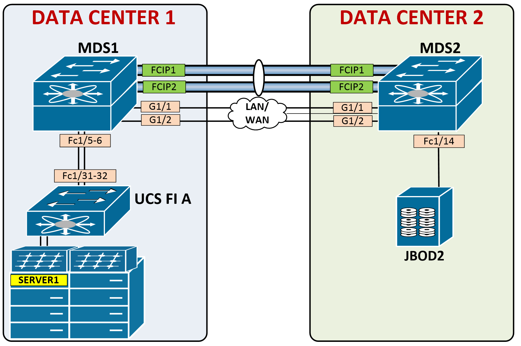
Below is the topology we’re looking at. We have a server in Data Center 1 that needs to attach to JBOD storage in Data Center 2 over the IP network.

To accomplish this, we’ll create an FCIP tunnel between MDS1 in Data Center 1 and MDS2 in Data Center 2.

Configuration Steps
1. Enable the fcip feature
2. Configure the Ethernet interface(s)
3. Configure the FCIP profile, assigning the IP address of the Ethernet interface (used as source)
4. Configure the FCIP interface, assigning the FCIP profile and the destination address
5. Enable the interface(s)
Let’s check out our current FCNS database, notice we only see pWWNs from our own Domain ID 0x01.
MDS1(config)# show fcns database

VSAN 101:
--------------------------------------------------------------------------
FCID        TYPE  PWWN                    (VENDOR)        FC4-TYPE:FEATURE
--------------------------------------------------------------------------
0x0100da    NL    21:00:00:1d:38:1c:79:0a                 scsi-fcp:target
0x0100dc    NL    21:00:00:1d:38:1c:6f:24                 scsi-fcp:target
0x0100e0    NL    21:00:00:1d:38:1c:78:fa                 scsi-fcp:target
0x0100e1    NL    21:00:00:1d:38:1c:78:d9                 scsi-fcp:target
0x0100e2    NL    21:00:00:1d:38:0e:d9:5e                 scsi-fcp:target
0x0100e4    NL    21:00:00:1d:38:1c:76:af                 scsi-fcp:target
0x0100e8    NL    21:00:00:1d:38:1c:77:04                 scsi-fcp:target
0x0100ef    NL    21:00:00:1d:38:1c:76:db                 scsi-fcp:target
0x010100    N     20:1f:00:2a:6a:46:89:00 (Cisco)         npv
0x010101    N     20:aa:00:25:b5:01:00:0f                 scsi-fcp:init fc-gs
0x010102    N     20:20:00:2a:6a:46:89:00 (Cisco)         npv

Total number of entries = 11
1. Enable the fcip feature
MDS1(config)# feature fcip

MDS2(config)# feature fcip
2. Configure the Ethernet interface(s)
There are few options here, you can configure a standard IP interfaces, VLAN sub-interface or a Port-channel. First, let’s configure a standard, single interface and run through a basic FCIP setup.
MDS1(config)# int g1/1
MDS1(config-if)# ip address 10.130.100.1 255.255.255.252
MDS1(config-if)# no shut

MDS2(config)# int gig1/1
MDS2(config-if)# ip address 10.130.100.2 255.255.255.252
MDS2(config-if)# no shut
Verify connectivity
MDS2(config-if)# ping 10.130.100.1 count 2
PING 10.130.100.1 (10.130.100.1) 56(84) bytes of data.
64 bytes from 10.130.100.1: icmp_seq=1 ttl=255 time=0.418 ms
64 bytes from 10.130.100.1: icmp_seq=2 ttl=255 time=0.364 ms

--- 10.130.100.1 ping statistics ---
2 packets transmitted, 2 received, 0% packet loss, time 999ms
rtt min/avg/max/mdev = 0.364/0.391/0.418/0.027 ms
In this topology, the MDS are actually directly connected. However, if the interfaces are not point-to-point, and are multiple layer 3 hops away, you need to configure routing. On an MDS, this is done slightly different than your typical IOS routes. Configure the route, your next-hop and the interface where your next-hop is located. For example:
MDS2(config)# ip route 10.150.100.2 255.255.255.255 10.130.100.254 interface g1/1
To display the routing table, you must envoke the ips (IP Storage) command. Notice the route does not show in the normal “show ip route”.
MDS2(config)# show ip route

Codes: C - connected, S - static

Default gateway is 10.60.0.1

C 10.130.100.0/30 is directly connected, GigabitEthernet1/1
C 10.60.0.0/24 is directly connected, mgmt0

MDS2(config)# show ips ip route interface gigabitethernet 1/1
Codes: C - connected, S - static

No default gateway

S 10.150.100.2/32 via 10.130.100.254, GigabitEthernet1/1
C 10.130.100.0/30 is directly connected, GigabitEthernet1/1
3. Configure the FCIP profile
This is the profile that will be referenced by the fcip interface. Tons of customization you can do here, which we’ll take a look at later on, but for now let’s configure the bare minimum – our source IP address.
MDS1(config-if)# fcip profile 1
MDS1(config-profile)# ip address 10.130.100.1

MDS2(config)# fcip profile 1
MDS2(config-profile)# ip address 10.130.100.2
4. Configure the FCIP interface
This is a virtual tunnel interface, similar to GRE. You need to reference your fcip profile and the IP address of your peer.
MDS1(config)# interface fcip 1
MDS1(config-if)# use-profile 1
MDS1(config-if)# peer-info ipaddr 10.130.100.2
MDS1(config-if)# ! NOTE: You could have added the "port" command after the IP to change the default tcp port 3225
MDS1(config-if)# no shut
MDS1(config-if)# exit

MDS2(config)# interface fcip 1
MDS2(config-if)# use-profile 1
MDS2(config-if)# peer-info ipaddr 10.130.100.1
MDS2(config-if)# no shut
MDS2(config-if)# 2014 Aug 18 09:58:35 MDS2 %PORT-5-IF_TRUNK_UP: %$VSAN 101%$ Interface fcip1, vsan 101 is up
2014 Aug 18 09:58:35 MDS2 %PORT-5-IF_TRUNK_UP: %$VSAN 1%$ Interface fcip1, vsan 1 is up
Verify the profile configuration
MDS1(config)# show fcip profile

-------------------------------------------------------------------------------
ProfileId       Ipaddr                                    TcpPort
-------------------------------------------------------------------------------
1               10.130.100.1                              3225
Verify the fcip tunnel status. You can see quite a bit of information here, especially for a summary command. Notice physical interface, peer ip address, trunking status, TE port type, bandwidth and calculated round trip time.
MDS1(config)# show fcip summary

-------------------------------------------------------------------------------
Tun prof    Eth-if    peer-ip       Status T W T Enc Comp  Bandwidth   rtt
                                           E A A            max/min    (us)
-------------------------------------------------------------------------------
1   1    GE1/1      10.130.100.2     TRNK  Y N N  N   N    1000M/500M  1000
And check this out, we now see the disks from MDS2:
MDS1(config)# show fcns database

VSAN 101:
--------------------------------------------------------------------------
FCID        TYPE  PWWN                    (VENDOR)        FC4-TYPE:FEATURE
--------------------------------------------------------------------------
0x0100da    NL    21:00:00:1d:38:1c:79:0a                 scsi-fcp:target
0x0100dc    NL    21:00:00:1d:38:1c:6f:24                 scsi-fcp:target
0x0100e0    NL    21:00:00:1d:38:1c:78:fa                 scsi-fcp:target
0x0100e1    NL    21:00:00:1d:38:1c:78:d9                 scsi-fcp:target
0x0100e2    NL    21:00:00:1d:38:0e:d9:5e                 scsi-fcp:target
0x0100e4    NL    21:00:00:1d:38:1c:76:af                 scsi-fcp:target
0x0100e8    NL    21:00:00:1d:38:1c:77:04                 scsi-fcp:target
0x0100ef    NL    21:00:00:1d:38:1c:76:db                 scsi-fcp:target
0x010100    N     20:1f:00:2a:6a:46:89:00 (Cisco)         npv
0x010101    N     20:aa:00:25:b5:01:00:0f                 scsi-fcp:init fc-gs
0x010102    N     20:20:00:2a:6a:46:89:00 (Cisco)         npv
0x0201da    NL    22:00:00:1d:38:1c:77:18                 scsi-fcp:target
0x0201dc    NL    22:00:00:1d:38:1c:77:05                 scsi-fcp:target
0x0201e0    NL    22:00:00:1d:38:1c:6e:b2                 scsi-fcp:target
0x0201e1    NL    22:00:00:1d:38:1c:78:e7                 scsi-fcp:target
0x0201e2    NL    22:00:00:1d:38:1c:6e:ba                 scsi-fcp:target
0x0201e4    NL    22:00:00:1d:38:1c:78:18                 scsi-fcp:target
0x0201e8    NL    22:00:00:1d:38:1c:76:d9                 scsi-fcp:target
0x0201ef    NL    22:00:00:1d:38:1c:3f:fc                 scsi-fcp:target

Total number of entries = 19
Let’s go ahead and setup a zoneset so our server can communicate with a remote disk from Data Center 2’s MDS. I’ll do inline zoning to speed this up:
zoneset name VSAN101 vsan 101
 zone name ESXi1-JBOD2-B-D1
    member pwwn 20:aa:00:25:b5:01:00:0f
    member pwwn 22:00:00:1d:38:1c:77:18
	zoneset activate name VSAN101 vsan 101
Let’s verify our host can now see the disk

Configure Active/Passive modes (Optional)
By default the interfaces are active, meaning they will actively attempt to connect to the their peer. If you place the interface in passive mode, it will wait for an IP connection from it’s peer. Useful if NAT is between the devices. Configured as:
conf t
 int fcip 1
  passive-mode
Another helpful tweak if you’re running NAT is to configure the number of TCP connections used for the FCIP link from 2 connections (which is the default – 1 for data, 1 for control) to 1 connection.
conf t
 int fcip 1
  tcp-connection 1
Configure MTU
The default MTU on these interfaces is 1500 bytes. In order to eliminate fragmentation, recommended to set the MTU to 2300 bytes. (2112 bytes for FC frame + 98 byte FCIP header, + some extra for good measure).

I just copied over a file to the newly mounted datastore – check out the number of reassembly frames we have due to the fragmentation caused by insufficient MTU:
MDS1(config-if)# sh interface fcip 1
fcip1 is trunking
    Hardware is GigabitEthernet
    Port WWN is 20:10:00:0d:ec:54:63:80
    Peer port WWN is 20:10:00:0d:ec:27:4f:40
    Admin port mode is auto, trunk mode is on
    snmp link state traps are enabled
    Port mode is TE
    Port vsan is 1
    Speed is 1 Gbps
    Trunk vsans (admin allowed and active) (1,101)
    Trunk vsans (up)                       (1,101)
    Trunk vsans (isolated)                 ()
    Trunk vsans (initializing)             ()
    Interface last changed at Mon Aug 18 10:00:34 2014

    Using Profile id 1  (interface GigabitEthernet1/1)
    Peer Information
      Peer Internet address is 10.130.100.2 and port is 3225
    Write acceleration mode is configured off
    Tape acceleration mode is configured off
    Tape Accelerator flow control buffer size is automatic
    FICON XRC Accelerator is configured off
    Ficon Tape acceleration configured off for all vsans
    IP Compression is disabled
    Maximum number of TCP connections is 2
    QOS control code point is 0
    QOS data code point is 0
    TCP Connection Information
      2 Active TCP connections
        Control connection: Local 10.130.100.1:65456, Remote 10.130.100.2:3225
        Data connection: Local 10.130.100.1:65458, Remote 10.130.100.2:3225
      2 Attempts for active connections, 0 close of connections
    TCP Parameters
      Path MTU 1500 bytes
      Current retransmission timeout is 200 ms
      Round trip time: Smoothed 2 ms, Variance: 1 Jitter: 150 us
      Advertized window: Current: 98 KB, Maximum: 24 KB, Scale: 5
      Peer receive window: Current: 25 KB, Maximum: 25 KB, Scale: 5
      Congestion window: Current: 44 KB, Slow start threshold: 112 KB
      Current Send Buffer Size: 24 KB, Requested Send Buffer Size: 0 KB
      CWM Burst Size: 50 KB
      Measured RTT : 0 us Min RTT: 0 us Max RTT: 0 us
    5 minutes input rate 368 bits/sec, 46 bytes/sec, 0 frames/sec
    5 minutes output rate 296 bits/sec, 37 bytes/sec, 0 frames/sec
      41067 frames input, 32231860 bytes
         1457 Class F frames input, 179824 bytes
         39610 Class 2/3 frames input, 32052036 bytes
         13576 Reass frames
         0 Error frames timestamp error 0
      623315 frames output, 1284418008 bytes
         1459 Class F frames output, 170136 bytes
         621856 Class 2/3 frames output, 1284247872 bytes
         0 Error frames
To change the MTU, run this on both MDSs’ physical interfaces:
MDS1(config)# int g1/1
MDS1(config-if)# switchport mtu 2300

MDS1(config)# int g1/2
MDS1(config-if)# switchport mtu 2300
Notice the MTU changed on both the gig interfaces AND the fcip interfaces:
MDS1# sh int g1/1 | i MTU
    MTU 2300  bytes
MDS1# sh int fcip 1 | i MTU
      Path MTU 2300 bytes
I just cleared the counters and am going to transfer another file. If the MTU is set properly we should see zero reassembly frames.

MDS1# show interface fcip 1 | i Reass
         0 Reass frames
Perfect!
FCIP using multiple interfaces
For redundancy purposes, or separate entry-points into the FC network, you may want to configure additional interfaces. Let’s add another physical interface with it’s own FCIP profile and FCIP interface. New topology looks like this:

MDS1:

interface g1/2
 ip address 10.130.101.1 255.255.255.252
 switchport mtu 2300
 no shut
!
fcip profile 2
 ip address 10.130.101.1
!
interface fcip2
 use-profile 2
 peer-info ipaddr 10.130.101.2
 no shut

MDS2:

interface g1/2
 ip address 10.130.101.2 255.255.255.252
 switchport mtu 2300
 no shut
!
fcip profile 2
 ip address 10.130.101.2
!
interface fcip2
 use-profile 2
 peer-info ipaddr 10.130.101.1
 no shut
Now we should have 2 FCIP tunnels
MDS1# show fcip summary

-------------------------------------------------------------------------------
Tun prof    Eth-if    peer-ip       Status T W T Enc Comp  Bandwidth   rtt
                                           E A A            max/min    (us)
-------------------------------------------------------------------------------
1   1    GE1/1      10.130.100.2     TRNK  Y N N  N   N    1000M/500M  1000
2   2    GE1/2      10.130.101.2     TRNK  Y N N  N   N    1000M/500M  1000
Nice. And check this out, we now have two equal cost paths to the remote Data Center MDS
MDS1# show fspf internal route vsan 101

FSPF Unicast Routes
---------------------------
 VSAN Number  Dest Domain   Route Cost    Next hops
-----------------------------------------------
         101      0x02(2)         1000        fcip1
                                              fcip2
Route Path Influence
We can of course influence path selection if we wanted to prefer one route over the other. As an example, let’s ensure that fcip1 is always taken unless there is a failure:
MDS1(config)# int fcip2
MDS1(config-if)# fspf cost 1100 vsan 101
MDS1(config-if)# exit
MDS1(config)# show fspf internal route vsan 101

FSPF Unicast Routes
---------------------------
 VSAN Number  Dest Domain   Route Cost    Next hops
-----------------------------------------------
         101      0x02(2)         1000        fcip1
FCIP using Port-Channels
When link failures should go uninterrupted, configure port-channels. To configure this, you actually place the virtual fcip interfaces in the port-channel, NOT the physical gig interfaces. Using our same configuration, simply add the fcip interfaces to a port-channel and “no shut” them to bring them back up.
MDS1:

MDS1(config)# int fcip1-2
MDS1(config-if)# channel-group 1
MDS1(config-if)# no shut

MDS2:

MDS2(config)# int fcip1-2
MDS2(config-if)# channel-group 1
MDS2(config-if)# no shut

2014 Aug 18 10:56:46 MDS1 %PORT-5-IF_TRUNK_UP: %$VSAN 101%$ Interface port-channel 1, vsan 101 is up
2014 Aug 18 10:56:46 MDS1 %PORT-5-IF_TRUNK_UP: %$VSAN 101%$ Interface fcip1, vsan 101 is up
2014 Aug 18 10:56:46 MDS1 %PORT-5-IF_TRUNK_UP: %$VSAN 101%$ Interface fcip2, vsan 101 is up
This automatically created the port-channel, as seen in the running config:
MDS1(config-if)# show run interface port-channel 1
interface port-channel 1
  switchport rate-mode dedicated
And now check out our routing using the single port-channel as the next hop:
MDS1(config-if)# show fspf internal route vsan 101

FSPF Unicast Routes
---------------------------
 VSAN Number  Dest Domain   Route Cost    Next hops
-----------------------------------------------
         101      0x02(2)          500 port-channel 1
FCIP using VLAN sub-interfaces
You may configure VLAN sub-interfaces in a scenario where the FCIP peers must be layer 2 adjacent and you need to trunk, or dare I say, OTV the VLAN between end-points. Or maybe you have segregated FCIP peers and need to use VLANs for the isolation. Whatever it may be, FCIP supports this functionality. I’m blowing away the old interface config and going to configure this as sub-interfaces instead, each with it’s own FCIP profile and FCIP interface.

Cleanup

no int po1
int g1/2
 no ip add
 shut
int g1/1
 no ip add

MDS1:

interface g1/1.100
 ip address 10.130.100.1 255.255.255.252
 no shut
interface g1/1.101
 ip address 10.130.101.1 255.255.255.252
 no shut
interface fcip 1
 no shut
interface fcip 2
 no shut

MDS2:

interface g1/1.100
 ip address 10.130.100.2 255.255.255.252
 no shut
interface g1/1.101
 ip address 10.130.101.2 255.255.255.252
 no shut
interface fcip 1
 no shut
interface fcip 2
 no shut

2014 Aug 18 11:05:20 MDS2 %PORT-5-IF_TRUNK_UP: %$VSAN 101%$ Interface fcip1, vsan 101 is up
2014 Aug 18 11:05:20 MDS2 %PORT-5-IF_TRUNK_UP: %$VSAN 1%$ Interface fcip1, vsan 1 is up
2014 Aug 18 11:05:35 MDS2 %PORT-5-IF_TRUNK_UP: %$VSAN 101%$ Interface fcip2, vsan 101 is up
2014 Aug 18 11:05:35 MDS2 %PORT-5-IF_TRUNK_UP: %$VSAN 1%$ Interface fcip2, vsan 1 is up

MDS2# show fcip summary

-------------------------------------------------------------------------------
Tun prof    Eth-if    peer-ip       Status T W T Enc Comp  Bandwidth   rtt
                                           E A A            max/min    (us)
-------------------------------------------------------------------------------
1   1    GE1/1.100  10.130.100.1     TRNK  Y N N  N   N    1000M/500M  1000
2   2    GE1/1.101  10.130.101.1     TRNK  Y N N  N   N    1000M/500M  1000
Score.
Advanced Configuration
As I mentioned earlier, there are tons of customizations you can configure. All of these below can be configured under the fcip profile.
You can optionally change the default FCIP port (TCP 3225)
fcip profile 1
 port 5555
TCP will wait 300ms before retransmitting. Configurable:
fcip profile 1
 tcp min-retransmit-time [250-5000]
If TCP retransmits 4 times without response it will close the connection. Configurable:
fcip profile 1
 tcp max-retransmission [1-8]
TCP will timeout the connection after 60 seconds of no received keep-alives. Configurable:
fcip profile 1
 tcp keepalive-timeout [1-7200]
TCP performance tuning over a WAN can turn into quite a lengthy conversation. From an FCIP configuration perspective, optimal TCP windows size is derived from 3 values: Maximum bandwidth allowed, minimum available bandwidth, and round trip time (RTT).
Configured as:
fcip profile 1
 tcp max-bandwidth-[k|m]bps X min-available-bandwidth-[k|m]bps X round-trip-time-[m|u]s X
The defaults are:
fcip profile 1
 tcp max-bandwidth-mbps 1000 min-available-bandwidth-mbps 2 round-trip-time-ms 10
Need extra send buffering beyond the normal TCP window size? Default is 0 KB
fcip profile 1
 tcp send-buffer-size [0-8192 KB]
Mark the FCIP packets with a DSCP value for QoS
fcip profile 1
 tcp qos control 3 data 5
Monitoring Congestion with TCP Congestion Window Monitoring (CWM). Enabled by default, configurable:
fcip profile 1
 tcp cwm
 tcp cwm burstsize [10-100 KB]
Enable compression
interface fcip 1
 ip-compression auto

MDS2(config-if)# show fcip summ

-------------------------------------------------------------------------------
Tun prof    Eth-if    peer-ip       Status T W T Enc Comp  Bandwidth   rtt
                                           E A A            max/min    (us)
-------------------------------------------------------------------------------
1   1    GE1/1.100  10.130.100.1     DOWN  N N N  N   A    1000M/500M  1000
2   2    GE1/1.101  10.130.101.1     TRNK  Y N N  N   N    1000M/500M  1000
Write Acceleration
This is a great option for FCIP over the WAN. This allows for multiple WRITE commands to be sent on behalf of the switch even though we haven’t received the R_RDY back from the remote switch. Takes into account the latency between FCIP peers. Excellent illustration of this on Cisco.com:

Note: write acceleration cannot be used with FSPF ECMP. You can, however, use port-channels. Keep this in mind if asked to configure FCIP optimally for a WAN connection.
conf t
 interface fcip 1
  write-accelerator

MDS1(config-if)# show fcip summary

-------------------------------------------------------------------------------
Tun prof    Eth-if    peer-ip       Status T W T Enc Comp  Bandwidth   rtt
                                           E A A            max/min    (us)
-------------------------------------------------------------------------------
1   1    GE1/1.100  10.130.100.2     TRNK  Y Y N  N   N    1000M/500M  1000
2   2    GE1/1.101  10.130.101.2     TRNK  Y N N  N   N    1000M/500M  1000
Let’s copy a file to the datastore again and verify we see exchanges processed by write acceleration.
MDS1(config-if)# show fcip host-map 1

 MAP TABLE (1 entries  TOTAL entries 1)

 OXID | RXID | HOST FCID| TARG FCID| VSAN |  FLAGS   | TA Flags | Index
------+------+----------+----------+------+----------+----------+---------
0x4020|0xffff| 0x010101 | 0x0201da |0x0065|0x00000103|0x00000000|0x00000380
Nice.
Tape Acceleration
Similar to standard write acceleration, we can enable tape acceleration. I won’t go much into this, just know it’s an option
conf t
 int fcip1
  write-accelerator tape-accelerator
Quick Template
Quick Template with 2 interfaces, preferring the path over G1/1 as the primary, using G1/2 as a backup.
MDS1:

feature fcip

int g1/1
 ip add 10.130.100.1 255.255.255.252
 switchport mtu 2300
 no shut

int g1/2
 ip add 10.130.101.1 255.255.255.252
 switchport mtu 2300
 no shut

fcip profile 1
 ip address 10.130.100.1

fcip profile 2
 ip address 10.130.101.1

int fcip 1
 use-profile 1
 peer-info ipaddr 10.130.100.2
 fspf cost 1 vsan 101
 no shut

int fcip 2
 use-profile 2
 peer-info ipaddr 10.130.101.2
 no shut


MDS2:

feature fcip

int g1/1
 ip add 10.130.100.2 255.255.255.252
 switchport mtu 2300
 no shut

int g1/2
 ip add 10.130.101.2 255.255.255.252
 switchport mtu 2300
 no shut

fcip profile 1
 ip address 10.130.100.2

fcip profile 2
 ip address 10.130.101.2

int fcip 1
 use-profile 1
 peer-info ipaddr 10.130.100.1
 fspf cost 1 vsan 101
 no shut

int fcip 2
 use-profile 2
 peer-info ipaddr 10.130.101.1
 no shut
Helpful show commands:
show fcip summary
show fcip profile
show int fcip 1 brief
show int fcip1 trunk vsan


Thanks a lot for the great post!
great info. Thanks for sharing this. Since there are two ways to change the FCIP port (first under FCIP profile and second under FCIP interface with peer- ip address command), are they to achieve the same purpose?
Thank you for the comments. What I would do in a situation where the port needed to be changed is configure it under the FCIP profile. Then, under the FCIP interface on the peer device, configure the destination port to match. If two-way communication initiated from either side needs to occur over the non-standard port, you would need to do the same on the other MDS.
What is the default cost of fcip link, any document to refer for default cost of fcip link?
Excellent Article! Well deserved CCIE DC!! Congrats.
Overlaid, I am finding all the information you post i.e..iscsi and now fcip to be great review, gap resolution and insures I understand the technology before moving on to other topics. I have my 5 day ipexpert boot-camp Aug 3rd to the 7th and then my first attempt at the lab on the 10th. Thanks for all your write-ups as I plan to review more.
Thanks
Thanks for the kind words, Zachary! Sounds like you have a solid plan, best of luck to you on your journey to mastery!
Excellent article ! Thank you
Maybe an aditionnal comment, you did not mention that you need to allow vsan 101 on port-channel (switchport trunk allowed vsan). Right ?