Part 6 of a series on data center networking for AI
You likely already know BGP EVPN/VXLAN as the tried and true approach to modern data center networking. If not, check out my older posts on Arista BGP EVPN for a primer. This post skips the primer and goes straight to what’s different and what isn’t when you apply it to a back-end GPU fabric.
Does the back-end fabric even need an overlay?
This is a good question to ask before reaching for EVPN/VXLAN at all. A single-tenant training cluster, meaning one customer, one job, dedicated hardware, very often runs a pure L3 BGP unnumbered underlay with no VXLAN overlay whatsoever. There’s no tenant to segment from another tenant, so the overlay’s core value proposition doesn’t apply, and skipping it avoids two costs: VXLAN’s roughly 50-byte encapsulation overhead per packet, and the encap/decap latency added at every hop – both of which cut against the microsecond-level determinism that adaptive routing (Part 5) and RDMA transport (Part 7, up next) are trying to protect. RoCEv2 technically does not need VXLAN to operate.
EVPN/VXLAN earns its place specifically in multi-tenant back-end fabrics, which, for an enterprise practice, is most of what you’ll actually design. When multiple business units, customers, or models share the same physical GPU fabric, you need a way to segment them logically without physically rewiring anything every time capacity gets reallocated. We need a way to prevent the noisy neighbor scenario discussed in Part 4. Neoclouds especially are a good example of multi-tenant back-end fabrics, offering AI-as-a-Service and hosting numerous customer operations on the same pools of GPUs across a common network.
Route types: what carries the weight here
This fabric almost always wants Symmetric IRB, not Asymmetric. The reasoning is a direct consequence of the rail-optimized topology.
Asymmetric IRB would require every leaf to carry every tenant’s L2VNI. Because the ingress VTEP performs both the bridge and route lookup and hands the packet to the egress VTEP already bridged into the destination’s L2 domain, the egress VTEP must locally have that L2VNI configured just to receive it, even if it hosts no local endpoints in that subnet. In a rail-optimized pod with many rail/leaf switches, that means stretching every tenant’s L2VNI to every leaf regardless of where that tenant’s GPUs actually live. Avoid this.
Symmetric IRB is the right default, because both ingress and egress VTEPs independently perform their own full bridge-route-bridge lookup using a shared L3VNI per VRF as the transit encapsulation, rather than the destination’s L2VNI. Only the L3VNI needs to be common across the fabric; each leaf only needs to locally know the L2VNIs for subnets it actually hosts.

Within Symmetric IRB, both Type 2 and Type 5 routes are used, for different reasons:
- Type 2 still carries the individual host route (/32 or /128), and in Symmetric IRB mode it carries a Router MAC extended community (RFC 9135) alongside the L3VNI, telling the remote VTEP which anycast gateway MAC to use for the final bridge hop after it performs its own local routing lookup. This is what lets inter-subnet, intra-tenant GPU-to-GPU traffic route correctly without the egress VTEP needing the source’s L2VNI at all.
- Type 5 advertises a whole prefix rather than a host. If a subnet is entirely confined to one VTEP (exactly the case for a rail switch whose GPU pool belongs to a single tenant), you can advertise that whole subnet as one Type 5 route instead of propagating individual Type 2 host routes for every GPU fabric-wide. This reduces route and FIB scale on every other VTEP in a pod with many hosts per rail.
One caveat or trade-off to this approach is that aggregating to Type 5 sacrifices per-host route visibility and the fast, host-specific withdrawal signal a Type 2 route provides when one GPU’s link drops. A covering prefix route doesn’t change when a single host inside it goes down. Given that GPU hosts are static, bare-metal endpoints (more on that below), this is usually an acceptable trade, but individual GPU health should come from fabric telemetry and monitoring, not from watching BGP route withdrawal at that granularity.
Type 2’s classic value proposition of MAC mobility as a workload migrates matters far less here than in a typical enterprise fabric. GPU servers are bare-metal and physically static so they don’t live-migrate the way a VM does. Segmentation and elastic reallocation (next), not mobility, are the reason to adopt EVPN for a GPU fabric.
Addressing: yes, GPUs have IPs
Every GPU’s dedicated NIC has an IP address, because RoCEv2 is structurally RDMA payload carried inside UDP inside IP. RoCEv1 was Ethernet-only and not routable; RoCEv2 was specifically redesigned to be L3-routable, using UDP destination port 4791. Every GPU’s NIC therefore has an IP in whatever VRF/VNI its tenant occupies – Tenant A’s GPUs in 10.100.0.0/16 under VNI 100, Tenant B’s in 10.200.0.0/16 under VNI 200, for example.
Let’s walk through the packet from the perspective of a VXLAN back-end fabric. You’ve got an outer layer and inner layer. The outer layer consists of a MAC header, IP header, and UDP header. The UDP header specifies destination port 4789 (the standard IANA port for VXLAN) and source UDP port dynamically calculated for load-balancing. We then hit the VXLAN header which contains the VNI flag necessary for tenant mapping. Once inside VXLAN, we have the inner MAC header, IP header, and UDP header. The inner UDP header is destination port 4791 (the standard IANA port for RoCEv2). Lastly, we have the RDMA payload which consists of the InfiniBand Transport Header and RDMA data itself.

Most GPU-to-GPU collective traffic is intra-VNI because every GPU participating in a given job belongs to the same tenant, so that traffic is bridged/routed within the same VNI across rail switches. Type 5 earns its keep mainly for inter-VRF reachability such as a tenant’s GPU pool reaching shared storage or the KV cache tier that lives in its own VRF, not for routing the bulk of GPU-to-GPU collective traffic itself.
GPU IP addressing in these fabrics is typically assigned by cluster provisioning tooling using a structured scheme that encodes physical position (e.g., rack, rail, GPU index) directly into the address, specifically so an engineer can infer physical location from an IP during troubleshooting.
Where segmentation happens: SuperNICs, DPUs, and the compute node
Before going further into the overlay, it’s worth reviewing where these VTEPs and NICs physically live on a server. Getting the vendor terminology right matters, because it’s easy to get backwards.
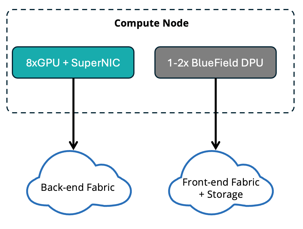
“SuperNIC” is NVIDIA’s term for the back-end, east-west NIC. This is the per-GPU RDMA adapter (ConnectX-7/8/9-based) purpose-built for the compute fabric, delivering RoCE connectivity between GPUs at up to 400-800Gb/s. BlueField DPUs handle the front-end (north-south) side, offloading networking, storage protocol termination, and security functions, typically one or two per server rather than one per GPU.
A note on DPUs: why not just call it a NIC?
A DPU is architecturally a small, independent computer sitting on the network card, not just an accelerated NIC. A BlueField-3 DPU packs 16 Arm cores and 32GB of onboard memory, running its own full software stack capable of hosting a virtual switch, firewall, and storage protocol termination entirely independently of the host CPU. A traditional NIC, even a “smart” one with hardware offloads, still fundamentally hands packets to the host CPU to process.
Why this matters for fabric design specifically:
- It’s a policy enforcement point you have to place in your design. In many deployments, VXLAN termination and microsegmentation are enforced on the DPU itself rather than the upstream leaf switch, meaning your EVPN VTEP boundary can literally be the server-resident DPU.
- It’s the trust boundary for bare-metal multi-tenancy. GPU workloads run on bare metal far more often than on VMs, precisely because virtualization overhead undermines the collective communication performance the fabric exists to deliver. Without a hypervisor to provide the usual VM-world isolation, the DPU fills that role instead – it’s what prevents one tenant’s bare-metal server from spoofing traffic or bypassing policy, since it’s a separate, isolated processor the tenant’s own OS has no access to.
- It typically carries its own manageable identity (i.e., its own IP, its own policy configuration) rather than behaving like passive cabling, which is a shift in operational model from a traditional server NIC.
- The architectural trend is toward unification. Newer platforms extend DPU-based policy control from the front-end into the back-end SuperNIC domain too, even though the actual RDMA data path still runs on the physically separate SuperNIC.
The DPU typically runs the vendor-supplied operating system or a specialized Linux-based operating system. On top of the base OS, DPUs frequently run network stacks like HBN (Host-based Networking) to manage BGP EVPN and data-plan forwarding directly on the DPU. The network stack, amongst other capabilities, rely on an orchestration layer or controller to centrally manage the scale of AI backend fabrics. Kubernetes is the most commonly leveraged, and increasingly packaged in network fabric platforms like Netris that abstract and automate large-scale AI data center networks.
Multihoming: the place this most diverges from enterprise practice
EVPN’s ESI active-active multihoming doesn’t apply the way you’d expect at the GPU-NIC layer.
Each GPU’s SuperNIC is single-homed to its designated rail switch, deliberately. RDMA queue pairs are bound to a single path, and NCCL’s rail-aware ring/tree construction (Part 3) depends on deterministic, predictable GPU-to-rail mapping. Introducing MLAG-style active-active hashing ambiguity at that layer undermines the exact determinism the rail design exists to provide. Where multihoming does still earn its keep is the front-end and storage networks, where redundant server NIC attachment is standard practice.
The value shows up in elastic, software-defined pool boundaries
Because VNI membership is a control-plane construct, not a physical wiring decision, GPUs can be reassigned between tenants – training vs. inference, Customer A vs. Customer B – by changing VXLAN/VRF mapping at the VTEP, with no recabling at all.
Tenant A and Tenant B GPUs can sit on the same rail switches and the same spine. Physical placement is completely decoupled from tenant boundary. That decoupling is what makes rapid reallocation possible.

The ability to rebalance capacity between training and inference, or between customers, on a timescale of minutes rather than a maintenance window, is one of the big selling points of EVPN/VXLAN for AI fabrics. It’s also the kind of operation modern intent-based fabric automation is built to drive: an operator declares “GPU 1 now belongs to the inference pool,” and automation pushes the corresponding VNI/VRF membership change.
Tying back to noisy neighbors (with a caveat)
VNI segmentation is also the natural attachment point for per-tenant QoS policy and rate-limiting at the VTEP. However, there are some things this mechanism can and can’t do, especially given how latency-sensitive decode traffic is.
VTEP-level rate-limiting is a coarse, admission-control mechanism with a guaranteed floor for one tenant, and a hard ceiling for another. It is enforced in hardware at line rate, adding negligible latency to traffic within policy. It only introduces queuing delay when a tenant’s traffic exceeds its allocated share, which is the scenario you want contained, because without the policy, that same contention degrades an innocent tenant’s inter-token latency anyway.
The fine-grained, microsecond-level reaction that protects inter-token latency is a different mechanism, a combination of DCQCN (Data Center Quantized Congestion Notification) and ECN (Explicit Congestion Notification)-based congestion control, plus the adaptive routing and flowlet load balancing from Part 5. That layer, not VTEP policing, is what keeps decode’s per-token latency predictable in real time. These mechanics will be covered in the next part of the series.
Configuration: same but different
Structurally, this is the EVPN/VXLAN we network engineers already know. It’s the same L2VPN EVPN address family, same VTEP/VNI/VRF/route-target constructs, same BGP unnumbered underlay patterns. However, some things need different tuning:
PFC and ECN marking, consistently mapped from DSCP to traffic class. A misalignment here between switch and NIC will break lossless behavior:
qos map dscp 26 to traffic-class 3qos map dscp 48 to traffic-class 7!qos profile QOS_ROCE_DCQCN qos trust dscp priority-flow-control on priority-flow-control priority 3 no-drop ! uc-tx-queue 3 random-detect ecn minimum-threshold 2000 segments maximum-threshold 10000 segments max-mark-probability 20 weight 0 random-detect ecn count!interface Ethernet2/5/1 mtu 9214 speed 200g-4 service-profile QOS_ROCE_DCQCN
BFD tied directly to remote VTEP reachability. This is a more aggressive, fabric-aware convergence mechanism than generic BGP timer tuning, updating hardware forwarding before the underlay route is even withdrawn from the FIB:
interface Vxlan1 bfd vtep evpn interval 100 min-rx 100 multiplier 3
Adaptive routing / flowlet load balancing – Arista EOS, for example, ships features for this called Dynamic Load Balancing (DLB) and Cluster Load Balancing (CLB), which rebalance ECMP traffic based on real-time port load rather than static hashing, the mechanism described in the previous post. Given that this is an evolving and platform-specific feature, it’s best to refer to the recent vendor documentation rather than this blog post, but below are some quick configuration examples.
DLB dynamically assigns packet flows to the least congested paths across Equal-Cost Multi-Path (ECMP) groups by tracking real-time queue and packet stats on egress ports.
ip hardware fib load-balance distribution dynamic average-traffic-weight 50 flow-set-size 4096 inactivity 10000 sampling-period 100 member-selection optimal timer
CLB is an RDMA-aware feature used at the Top-of-Rack (ToR) or spine level to inspect RoCEv2 queue-pair entropy and intelligently distribute massive elephant flows without causing packet polarization.
load-balance cluster enabled ! Optional tuning parameters depending on architecture and EOS version exit
Takeaways
- Ask “single-tenant or multi-tenant?” before defaulting to EVPN/VXLAN on a back-end fabric. Single-tenant training clusters often skip the overlay entirely.
- Default to Symmetric IRB, not Asymmetric – the rail-optimized topology makes stretching every L2VNI to every leaf an unnecessary burden.
- Lead with Type 5 subnet aggregation and elastic VNI reallocation as the value proposition for an EVPN/VXLAN back-end. Type 2 MAC mobility barely applies to static, bare-metal GPU hosts.
- Don’t use ESI active-active multihoming at the GPU-NIC layer. Rail links are deliberately single-homed for RDMA determinism; multihoming’s value here is on the front-end and storage networks.
- Know where SuperNICs and DPUs sit and what each does – the DPU is often your VTEP and policy enforcement point, not the upstream leaf switch.
Next in this series: RDMA transport deep dive – RoCEv2 vs. InfiniBand, and the DCQCN/ECN/PFC mechanics previewed throughout this post.


