Part 2 of a series on data center networking for AI
Before you can reason about fabric design or traffic patterns, you need to know where the network actually starts and stops relative to a GPU. A lot of network engineers new to this space assume “the network” begins at the NIC the way it always has, but in GPU systems, a huge amount of what looks like network traffic never touches a NIC at all. Getting this boundary right changes how you think about everything downstream, and clears up misconceptions about where your networking expertise is valued and warranted, and where you can set it aside.
The GPU’s other bus: PCIe
Every GPU sits on a PCIe bus inside its server, connecting it to the CPU, system memory, storage, and NICs, which is the same bus architecture that’s always existed, just faster. Current-generation servers run PCIe Gen5 (many still on Gen4), typically x16 lanes per device, delivering roughly 64GB/s of bidirectional bandwidth between a GPU and the rest of the server on Gen5. That’s GBps not Gbps which equates to 512Gbps (64 x 8 = 512), which sounds like a lot, until you see what it’s competing with.

A quick note on NUMA locality
NUMA locality describes how close a CPU is to the specific memory it is trying to use in a Non-Uniform Memory Access system. Accessing local memory attached directly to a CPU core’s own NUMA node is fast, while accessing remote memory on another node takes more time. So what does this have to do with GPUs?
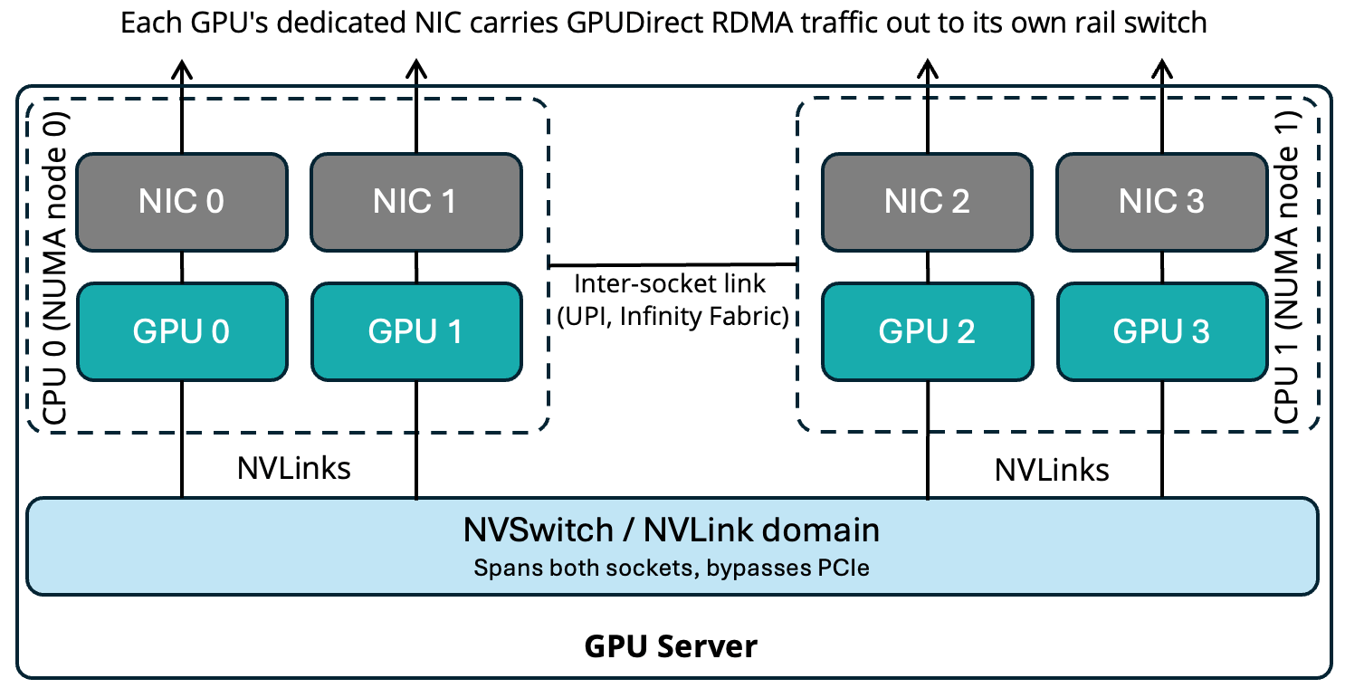
A common AI server build such as the NVIDIA HGX platform features 8 GPUs, 8 NICs, and 2 CPU sockets, with each socket’s PCIe root complex serving a subset of the GPUs, which is commonly 4 GPUs and 4 NICs split across the two sockets. Multiple GPUs sharing a socket is the normal, age-old NUMA approach. The risk is a mismatched GPU-NIC pairing: if a GPU is wired to one socket but its dedicated NIC is wired to the other, every packet that GPU sends has to cross the inter-socket interconnect (Intel UPI or AMD Infinity Fabric) before it even leaves the server, which adds latency, contention with unrelated cross-socket memory traffic, and turns that one GPU into a potential straggler in every collective operation, invisible from the switch or rail level.

Well-designed GPU servers (DGX-class and OCP equivalents) deliberately pair each GPU with a same-NUMA-node NIC to avoid this problem. It’s worth knowing because when you’re troubleshooting “why is this GPU pair slower than that one,” the answer sometimes lives inside the server chassis, not in the fabric.
NVLink and NVSwitch: the network’s shadow competitor
Inside the server, GPUs don’t talk over the network at all. A modern GPU server (think NVIDIA HGX/DGX-class or an OCP equivalent) has its GPUs interconnected by NVLink, with an NVSwitch ASIC acting as a non-blocking crossbar between them.

NVLink is NVIDIA’s proprietary GPU-to-GPU interconnect, and NVSwitch is the switching silicon that lets multiple GPUs talk to each other. Current generations deliver upward of 900GB/s per GPU: more than an order of magnitude beyond PCIe, and well beyond even an 800Gb/s network NIC which tops out around a measly 100GB/s. The newest generation delivers 3,600GB/s of bandwidth per GPU.
The consequence for network design: the network fabric will never carry traffic between two GPUs that share an NVLink domain. The NVIDIA Collective Communications Library (NCCL), which I’ll cover in Part 3, is topology-aware and always prefers the fastest available path, so any GPU pair within the same NVLink domain, including intra-node and, increasingly, intra-rack pairs with NVL72-style systems where NVSwitch spans multiple chassis, communicates entirely over NVLink. The network only ever carries traffic that has nowhere else to go, such as communication between GPUs in different NVLink domains. This is why the software layer deliberately structures its communication patterns to keep as much traffic as possible inside NVLink domains, sending only the minimum necessary volume out over the “real” physical network.
When you hear NVLink and NVSwitch and start wondering how you configure these things, take a step back. You’ll rarely deal with the mechanics of these components, since they’re built inside the compute platforms themselves, and you may never touch them at all. Hyperscalers are more likely to be an exception. For most enterprises, these aren’t network “devices” you’d be expected to design and configure from scratch the way you would in traditional networks.
GPUDirect RDMA: the NIC talks straight to GPU memory
Without GPUDirect RDMA, moving data from GPU memory onto the wire looks like this: GPU memory > copy to system RAM > CPU involvement > copy to NIC buffer > onto the wire. Every one of those hops adds latency and burns CPU cycles and PCIe bandwidth that the workload doesn’t have to spare.
GPUDirect RDMA removes the middle steps. The NIC’s DMA engine is given direct access to GPU memory (via the GPU’s PCIe base address register (BAR) being exposed to the NIC), so data moves GPU memory > NIC > wire directly, with no CPU involvement and no bounce through system RAM. This is vital in AI network design because without it, the CPU becomes an unpredictable bottleneck that undermines the entire premise of a low-latency fabric. The InfiniBand and RoCEv2 networks we’ll discuss later are built to carry this RDMA traffic across a network fabric.
(There’s a sibling technology, GPUDirect Storage, which does the same trick for NVMe storage-to-GPU transfers. It’s worth knowing the name exists because I’ll touch on this in a later post. However, it’s less central to the data center networks for AI network design work we’re discussing here.)
One NIC per GPU: the multi-rail pattern
High-end GPU servers dedicate one NIC per GPU rather than sharing NICs across multiple GPUs – commonly eight GPUs paired with eight NICs, sometimes with an additional NIC or two reserved for storage and management traffic, kept separate from the compute fabric.
The reasoning is if two GPUs shared a single NIC, their traffic would contend for the same physical port precisely when synchronized communication demands maximum parallelism, reintroducing the exact bottleneck this entire architecture exists to avoid.
SmartNICs and DPUs (e.g., NVIDIA BlueField) enter the picture here too, particularly in multi-tenant environments. A Data Processing Unit (DPU) can offload virtual switching, encryption, storage protocols, and tenant isolation from the host CPU. This offload capability matters far more in enterprise and multi-tenant environments running multiple business units or customers on shared GPU infrastructure than it does in a single-tenant hyperscale training cluster. The DPUs often become integrated as a part of the network, for example with the VXLAN Tunnel Endpoint (VTEP) on the DPU itself. More on this in an upcoming post where I’ll discuss the EVPN control plane.
From NIC to rail: the physical wiring pattern
This is where server-internal design meets fabric design. Rather than connecting all the NICs from a server to the same leaf switch, each GPU’s dedicated NIC connects to its own designated leaf switch, called a rail. GPU 0’s NIC, across every server in the pod, lands on Rail switch 0. GPU 1’s NIC lands on Rail switch 1. This pattern repeats identically across the entire pod.

GPU 0 on one server and GPU 0 on any other server are always exactly one hop apart, no matter how large the pod grows. The collective communications library (NCCL) constructs its communication patterns knowing this structure in advance, rather than hoping hash-based load balancing cooperates. Communication between different-numbered GPUs on different servers still has to cross rails via the spine, and this is the traffic that benefits most from careful topology and congestion-control design, which I’ll cover in depth in later posts in this series.
A note on the physical layer
At 400G and 800G speeds, the cabling choice is a design constraint. Direct-attach copper (DAC) is cheap and low-latency but distance-limited to a few meters; active optical cables (AOC) and pluggable transceivers extend reach across a row or between racks at higher cost. Within a rail-optimized rack, DAC often handles GPU-to-leaf runs where distance allows, while longer leaf-to-spine runs push toward optics. This becomes especially relevant when we get to emerging directions like co-packaged optics later in the series.
Takeaways
- Know where your fabric actually starts. A substantial share of GPU-to-GPU communication never leaves the server, so don’t design the network as if it needs to carry that traffic.
- NUMA and PCIe placement inside the server is a network-adjacent design decision. A mismatched GPU-NIC pairing across sockets creates latency that looks like a fabric problem but isn’t.
- Multi-rail, one-NIC-per-GPU is the default pattern for good reason. Resist the instinct to consolidate NICs the way you might on a general-purpose server fleet.
- In multi-tenant enterprise environments, DPUs and SmartNICs are the isolation and offload lever. More relevant to enterprise deployments than to single-tenant hyperscale designs, and increasingly common in AI data center builds.
Next in this series: the collective communication operations themselves such as all-reduce, all-gather, reduce-scatter, and all-to-all, and exactly how each one turns into a distinct traffic pattern on the wire.

